- Joined
- Jan 9, 2020
- Messages
- 10,378
- Points
- 938

With so much being said about the YuanQing Bluenose and with the tremendous response the kit has caused on SOS - and other forums - the time has come to start the actual building of the kit. I am not going to say anything more about the Kit Review - it available on the Bluenose Group Build and under the Kit Review section where it has rewritten all SOS records for a kit review. (The last time I checked, the views were well over 9 000!)
As promised, we started doing the translation (thanks Admiral Anna), but I quickly realised that the only way to create a truly accurate instruction manual is in conjunction with the actual build. Only there will we discover the pitfalls that cause the downfall of many an instruction manual.
So let's see how the assembly the building jig pans out. First off, the kit provides you with 4 very large-sized sheets with drawings and plans on both sides - thus 8 in total. Two of those are important and pertain to the jig assembly. First, there is the Parts Checklist and secondly, the actual jig-assembly drawing itself.
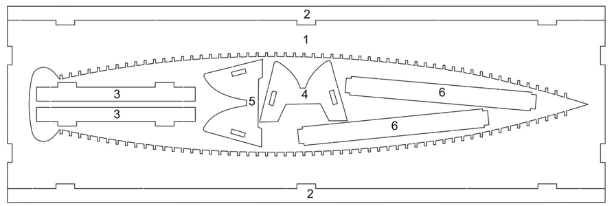
The above picture from the Parts Check-list, shows the sheet used for the jig assembly. I am so happy to report that it is NOT MDF (highly toxic when sanded or filed and don't get water near it) or Plywood (susceptible to warping), but a 4mm thick Sycamore sheet of wood.
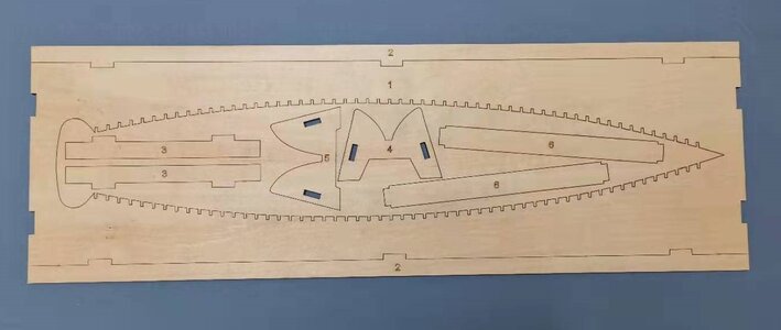
In real life, this is what the drawing shows. Parts 1, 2 and 3 which will be needed for the jig are clearly marked.
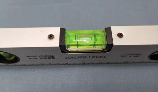
The first thing to do before any jig assembly (or keel and rib-assembly for that matter) takes place, is to make sure that your working surface is absolutely level.
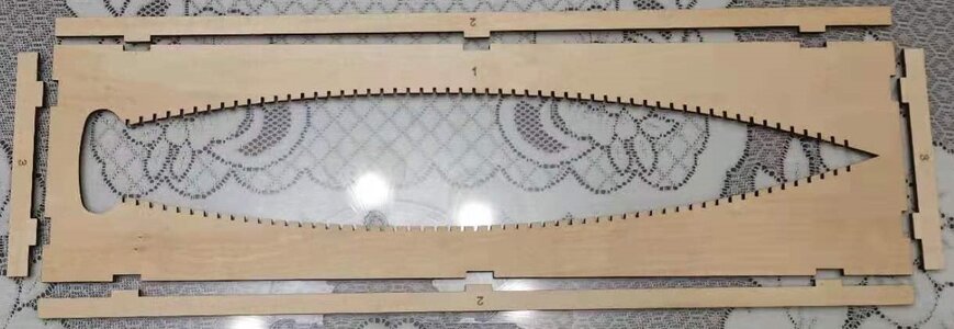
Parts #2 and #3 were then removed the sheet using an X-Acto knife which was as easy falling out of a tree. The laser-cutting is very precise, and once you have cut through the tabs, the parts come out easily. I do apologise for my luxurious blue bedsheet that went AWOL for this picture, but it was subjected to a quick ironing by the Admiral.
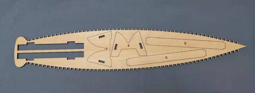
The centre piece removed from the board looks like this. Note that the other two empty slots belong Part #3 which are used as end pieces in the jig.
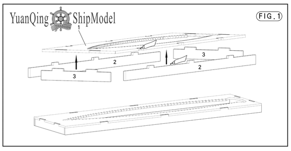
This then the actual assembly drawing which shows Parts #2 glued to the board (Part #1) lengthwise and Parts #3 which close the "box" at the end. Assembly of the jig was very easy and everything fit together very well. Here, I did not bother with sanding away the laser char, as it is purely cosmetic and bears no influence of the functionality of the jig.
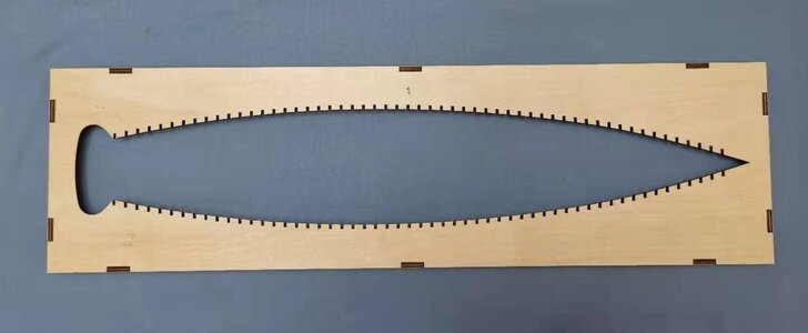
The assembled jig from the bottom (yes I am right!)
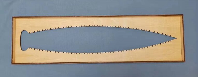
And from the top. Remember, this is the side on which we will be building - hence its designation as the "top" side.
And that concludes the jig assembly. All done in a morning which includes the drying time of the PVA. It was all very straightforward, and will not present any problems. Next up, YuanQing suggests starting with the assembly of the ribs - and they are right of course - but I found the keel more interesting!
Thank you all so much for watching and following - and for those of you who have ordered this kit - I believe you are in for a treat!
Kind regards - Heinrich
As promised, we started doing the translation (thanks Admiral Anna), but I quickly realised that the only way to create a truly accurate instruction manual is in conjunction with the actual build. Only there will we discover the pitfalls that cause the downfall of many an instruction manual.
So let's see how the assembly the building jig pans out. First off, the kit provides you with 4 very large-sized sheets with drawings and plans on both sides - thus 8 in total. Two of those are important and pertain to the jig assembly. First, there is the Parts Checklist and secondly, the actual jig-assembly drawing itself.

The above picture from the Parts Check-list, shows the sheet used for the jig assembly. I am so happy to report that it is NOT MDF (highly toxic when sanded or filed and don't get water near it) or Plywood (susceptible to warping), but a 4mm thick Sycamore sheet of wood.

In real life, this is what the drawing shows. Parts 1, 2 and 3 which will be needed for the jig are clearly marked.

The first thing to do before any jig assembly (or keel and rib-assembly for that matter) takes place, is to make sure that your working surface is absolutely level.

Parts #2 and #3 were then removed the sheet using an X-Acto knife which was as easy falling out of a tree. The laser-cutting is very precise, and once you have cut through the tabs, the parts come out easily. I do apologise for my luxurious blue bedsheet that went AWOL for this picture, but it was subjected to a quick ironing by the Admiral.

The centre piece removed from the board looks like this. Note that the other two empty slots belong Part #3 which are used as end pieces in the jig.

This then the actual assembly drawing which shows Parts #2 glued to the board (Part #1) lengthwise and Parts #3 which close the "box" at the end. Assembly of the jig was very easy and everything fit together very well. Here, I did not bother with sanding away the laser char, as it is purely cosmetic and bears no influence of the functionality of the jig.

The assembled jig from the bottom (yes I am right!)

And from the top. Remember, this is the side on which we will be building - hence its designation as the "top" side.
And that concludes the jig assembly. All done in a morning which includes the drying time of the PVA. It was all very straightforward, and will not present any problems. Next up, YuanQing suggests starting with the assembly of the ribs - and they are right of course - but I found the keel more interesting!
Thank you all so much for watching and following - and for those of you who have ordered this kit - I believe you are in for a treat!
Kind regards - Heinrich


