I prefer hand tools/files whenever possible as there is more tactile feeling than a power tool for a sense of touch. RichCool!
-

Win a Free Custom Engraved Brass Coin!!!
As a way to introduce our brass coins to the community, we will raffle off a free coin during the month of August. Follow link ABOVE for instructions for entering.
-

PRE-ORDER SHIPS IN SCALE TODAY!
The beloved Ships in Scale Magazine is back and charting a new course for 2026!
Discover new skills, new techniques, and new inspirations in every issue.
NOTE THAT OUR FIRST ISSUE WILL BE JAN/FEB 2026
- Home
- Forums
- Ships of Scale Group Builds and Projects
- Bluenose PoF Group Build
- Bluenose Group Build Logs
You are using an out of date browser. It may not display this or other websites correctly.
You should upgrade or use an alternative browser.
You should upgrade or use an alternative browser.
Do you have an email address for Yuanqing? I need some support. Thanks
Hey Heinrich. Great explanation on this - thanks. I actually separated all my keel sections yesterday and they are on the dining room table. Used my battery operated Dremel on the lowest setting with the 260 sanding barrel it was PERFECT for removing the char and the tabs as was cleaning the parts up with acetone which slightly raises the grain and removes any char residue that got on the faces of the keel pieces! Worked like a charm and is what I always use as well after sanding to clean and remove the fine sanding dust.
Question on the glueing of the narrow 20 and 17 pieces and in general, glueing the pieces in general. Normally when I glue large wood pieces together, I apply a film of glue to the entirety of both surfaces and mate them together - which guarantees a forever bond and which also causes squeeze-out when clamped. The squeeze-out is then easily scraped and sanded off. But that can't be the case with these fragile and narrow parts especially the ones that must have the notches lined up - so in essence - what type/best brand of glue does one use, how does one consistently glue these parts together on their long lengths to maintain consistent adhesion and part orientation along the lengths, how much glue does one use, and what type of container does one use to apply the glue? I typically use yellow titebond 3 but that would not work here! Thanks as always.
Question on the glueing of the narrow 20 and 17 pieces and in general, glueing the pieces in general. Normally when I glue large wood pieces together, I apply a film of glue to the entirety of both surfaces and mate them together - which guarantees a forever bond and which also causes squeeze-out when clamped. The squeeze-out is then easily scraped and sanded off. But that can't be the case with these fragile and narrow parts especially the ones that must have the notches lined up - so in essence - what type/best brand of glue does one use, how does one consistently glue these parts together on their long lengths to maintain consistent adhesion and part orientation along the lengths, how much glue does one use, and what type of container does one use to apply the glue? I typically use yellow titebond 3 but that would not work here! Thanks as always.
- Joined
- Jan 9, 2020
- Messages
- 10,566
- Points
- 938

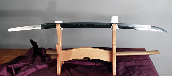
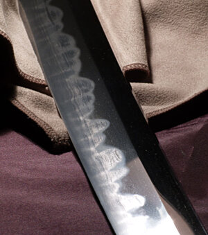
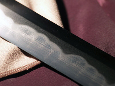
Hi Joe. Let me first comment on that absolutely beautiful Katana! That is a blade (for want of a better word) to be exceptionally proud of - the history and culture behind it is just beyond comparison. And you are right - that hamon is beautifully executed. South Africa has a plethora of excellent custom knife-makers - my favorite one is a gentleman with the name of Theuns Prinsloo (I will some time in the future show you some of his work).
I use ordinary white PVA but because I am in China, I use a Chinese brand which is obviously does not help you. I tried Titebond 3 and I really did not like it. I just applied the glue to one surface with a toothpick and then just gently smeared the applied glue flat/thinner with my finger. As I told you before, I build very unscientific and very simple - so I have no special containers or applicators.
I use ordinary white PVA but because I am in China, I use a Chinese brand which is obviously does not help you. I tried Titebond 3 and I really did not like it. I just applied the glue to one surface with a toothpick and then just gently smeared the applied glue flat/thinner with my finger. As I told you before, I build very unscientific and very simple - so I have no special containers or applicators.
This might help a bit.! On my Bluenose I am using Aliphatic Resin from "Deluxe Materials". I really like this stuff, and as Heinrich , I dab it on then spread with a finger. It's waterproof and used by instrument makers so be careful for those mistakes may be hard to undo 
Wonderful pictorial Heinrich. Although a novice, I actually assembled my ribs differently. I glued the lower center front and back sections (I call them yokes) together first and aligned them by the top and bottom indents. The longer extensions of the front yoke section then provided more glue surface and spot on alignment via the bevel lines for the shorter rear arms. Once these were glued, they subsequently provided more glue surface and bevel line alignment for the two longer front arms. I did it this way as the butt joints between the front arms and yoke were proving far too weak and kept coming apart - which was problematical.FRAMES PART 1
PLEASE NOTE THAT FRAME CONSTRUCTION IS THE FIRST PART OF THE BLUENOSE BUILD - I have only done the keel first, because of sentimental reasons. For me the keel-laying was a symbolic sign that harks back to the history of this great schooner.
In this first Part I will show you what can be called the "Preparatory" stage for frame construction and also offer some explanations.
The frames come in a package which is marked with the #7 so this is all that you need to remove from the kit box.
View attachment 199870
Here you can clearly see the #7 on the bubble wrap. Yours will be a lot neater than mine - we opened this beforehand for the kit review.
View attachment 199875
With the bubble-wrap removed, you will be presented by this. simply cut open the plastic wrapping and remove whatever sheet containing the frame that you want to build, from it.
View attachment 199876
This is what your frame sheet looks like. In the right, upper hand corner you can clearly see the number of the frame identified. Each frame consists of two halves which are made up of three parts each. In each case there will be a centre-section and the two ribs that go on either side of the centre-section. I chose Frame #8 to begin with as the #8 is deemed a very lucky number in China.
Now is also the time to open your instruction manual containing the information on frame construction. One of the two manuals is specifically dedicated to this. Opening the first page - you will incidentally see Frame #8 first (for reasons as described above)
View attachment 199877
You will then be faced with two full-scale (1:1) drawings of the frames (one from the front, one from the back) and two sets of hieroglyphics!One in Chinese and one my hand-scribbled translation attempts. Not to despair - have a look at the next image.
View attachment 199879
Here you have a duplicate of the previous image. Let's work from the top of the page down. In red, you will clearly see "Front" and "Rear" to indicate which is which.
Next, you will see as indicated by the red lines what is described by YuanQing as the "Cutting Lines" (we will get to those later).
In line with that, it is obvious that we are working with Frame #8.
Below that, and marked by the yellow lines is what YuanQing calls the markings for the "Load Bearing Line". The next picture will indicate clearly what that is meant by that and its function later in the build.
The Pink lines at the bottom of the page indicate the bevel lines which are also clearly marked on the frames themselves.
View attachment 199882
Above I mentioned the "Load Bearing Line". In essence these are the markings that indicate the exact positioning of the two "Load Bearing Beams" which are to be installed later in the build. For our purposes now though, we just need to know what those markings mean and realize that they will play a part later on. In my next posting - which I hope to do tomorrow night (China time), we will start the actual construction of the frames.
Until tomorrow.
Thank you all for watching, for your tremendous support and for being part of this great Bluenose family!
Heinrich
Wow - great tip Heinrich!Hello Everyone
I want to share my "modification" that I mentioned last night. As you will recall, I explained how Parts #19 and #65 are combined (by gluing together) and then beveled.
View attachment 202508
Here you can see how the #19/65 combination is glued to the keel - one on either side. For this, YuanQing has provided us with with a 1:1-scale drawing. This allows you to place the keel exactly over the drawing and then align the combined Part #19/65 in its correct - position. No problem here!
But now let's take a look at the picture below.
View attachment 202507
On my keel assembly - and I have no idea if this is peculiar to the way that I built the keel - the unbeveled part of Part #18 does not lie level with the sternpost - it is slightly higher (it is the same on the other side). This means that my combination Part #19/65 will not lie flush with the unbeveled section of Part #18 and the sternpost. My solution was as follows:
View attachment 202509
I simply cut out the piece (as is indicated in yellow) on the backing sheet which housed Part #18 making sure that I followed the exact lines of Part #18.
View attachment 202510
It is better illustrated on this drawing where the two sections that I cut out are marked in red and pointed out by the bold, black arrow. These I then glued onto the sternpost and once the glue had dried I cut off the overhang at the back.
View attachment 202511
The inserted piece on the Port Side.
View attachment 202512
And on the starboard side.
Now everything is flush and ready to accommodate our combination part #19/65. As mentioned before, I don't know if you will be affected by the same issue, but if you are, you know what you can do.
Kind regards - Heinrich
Hey Heinrich,
I know you have been thinking about your next project after the WB, any chance you will finish the BN?
I know you have been thinking about your next project after the WB, any chance you will finish the BN?
Hey Heinrich. Not to be a pest and don't know if you saw my other query but was wondering what the status is of the replacement keel parts 17 and 18 and the #8 rib block. I'm working on assembling the ribs as we speak and then still have to shape them so am a ways off but really want to get the keel completed. I know things are likely still harried over there with covid but let me know when you can. Thanks.
I feel I must comment because as a novice, I don't want other folks to do what I did - glue 17 and 18 together into one piece before installing it on the base keel section. Reason being that with the one piece - my teeth did not line up. As Heinrich has pictured, best to attach these one piece at a time as they obviously need to independently flex to get the teeth to line up. If there ends up being a gap between the two pieces, you can easily fill it with a piece of scrap.Hello Dear Friends
First I have to thank you all for your tremendous response to and support of this build log - it was no surprise that Bluenose occupied the #1 Spot on the SOS Charts for the Most Viewed Topic!
View attachment 198502
Weekends are by far my busiest as far as my teaching schedule goes, so please bear with me for not being able to give you a substantial update. However, some progress was made and all is still going well so far.
View attachment 198505
To recap, we have now finished the bottom-end of the keel assembly which comprises of the inner keel and two "outer " keels - Port- and Starboard Side. The newly added parts (#20 and #21) are the ones marked in red and green on the drawing above. Now was also the right time to remove the laser char on the bottom side of the keel.
Next in line is the the installation of the outer keels on the top part of the keel assembly. To see how these look, we revert again to our Parts Inventory.
View attachment 198506
You will see that there are obviously two drawings - one each for the Port-and Starboard sides. For our immediate purpose, we are only going to work with Parts #17 and #18. Part #19 will form part of the transom assembly and later and should not be cut from the sheet for the time being.
View attachment 198509
There are obviously also two wooden sheets supplied - this one shows the Port Side. Notice that I have marked the sheet with the word "Bokant" (Afrikaans) in the far right, lower corner. "Bokant" means "Top Side" and is marked to indicate the side that will be visible after assembly, i.e. the "outer" side. Also note that I have clearly marked each part to avoid any possible confusion later on.
View attachment 198512
Here the two parts are removed from the sheet and placed above the keel in their correct designated positions. Part #17 will be installed from the midships position towards the bow-end whilst Part #18 will run from midship towards the stern. After I had removed the char (ONLY ON THE BOTTOM END) of Part #17, I applied a fine layer of PVA glue (I use my finger for this to ensure that it is applied evenly) taking great care that no glue got into any of the notches. Then I left the glue to dray for approximately 15 minutes. This makes the glue slightly more tacky which means the part does not slide around too much while being attached to the inner keel portion.
CAUTION: Take your time with this and make sure that the notches are PERFECTLY aligned. This is crucial as these steps will ultimately ensure that our frames are seated correctly and securely. If any glue does get into any of the notches REMOVE IMMEDIATELY with a damp cloth.
View attachment 198519And there you go! Gents, the fit on this kit has been PERFECT so far. The notches line up beautifully. Tomorrow morning I will attach Part #17 on the Port Side. I do not like doing this in artificial light, because you can imagine that any shadow or reflection cast by light will wreak havoc on the notch-alignment. I have already discovered that if you work slowly and as accurately as you can, the kit will deliver the goods.
Fire away with all those comments and questions. I am at your call.
- Joined
- Jan 13, 2023
- Messages
- 30
- Points
- 48

Thank you took me awhile but finally got it. Going to be a great buildHi Heinrich
Nice building log. I have a question.
Is the jig in your posted picture in the correct position ?
The sides I am pointing with my arrow i belive have to go against the bench. Those laterals walls (arrow) are a type of "legs" to separate the jig from the bench....correct ?
In that way the point of the ribs aren't against the bench. Or Am I missing something ?
View attachment 197926
This is your posted jib picture. Looks like goes as I have described.
View attachment 197927
Cheers
Daniel
Ps: a picture of the MARMARA jig showing what I tried to explain on the above picture with the arrow.
View attachment 197928
- Joined
- Oct 1, 2023
- Messages
- 2,035
- Points
- 488

I finally found your build log for the Bluenose.With so much being said about the YuanQing Bluenose and with the tremendous response the kit has caused on SOS - and other forums - the time has come to start the actual building of the kit. I am not going to say anything more about the Kit Review - it available on the Bluenose Group Build and under the Kit Review section where it has rewritten all SOS records for a kit review. (The last time I checked, the views were well over 9 000!)
As promised, we started doing the translation (thanks Admiral Anna), but I quickly realised that the only way to create a truly accurate instruction manual is in conjunction with the actual build. Only there will we discover the pitfalls that cause the downfall of many an instruction manual.
So let's see how the assembly the building jig pans out. First off, the kit provides you with 4 very large-sized sheets with drawings and plans on both sides - thus 8 in total. Two of those are important and pertain to the jig assembly. First, there is the Parts Checklist and secondly, the actual jig-assembly drawing itself.
View attachment 197808
The above picture from the Parts Check-list, shows the sheet used for the jig assembly. I am so happy to report that it is NOT MDF (highly toxic when sanded or filed and don't get water near it) or Plywood (susceptible to warping), but a 4mm thick Sycamore sheet of wood.
View attachment 197809
In real life, this is what the drawing shows. Parts 1, 2 and 3 which will be needed for the jig are clearly marked.
View attachment 197810
The first thing to do before any jig assembly (or keel and rib-assembly for that matter) takes place, is to make sure that your working surface is absolutely level.
View attachment 197811
Parts #2 and #3 were then removed the sheet using an X-Acto knife which was as easy falling out of a tree. The laser-cutting is very precise, and once you have cut through the tabs, the parts come out easily. I do apologise for my luxurious blue bedsheet that went AWOL for this picture, but it was subjected to a quick ironing by the Admiral.
View attachment 197812
The centre piece removed from the board looks like this. Note that the other two empty slots belong Part #3 which are used as end pieces in the jig.
View attachment 197813
This then the actual assembly drawing which shows Parts #2 glued to the board (Part #1) lengthwise and Parts #3 which close the "box" at the end. Assembly of the jig was very easy and everything fit together very well. Here, I did not bother with sanding away the laser char, as it is purely cosmetic and bears no influence of the functionality of the jig.
View attachment 197814
The assembled jig from the bottom (yes I am right!)
View attachment 197815
And from the top. Remember, this is the side on which we will be building - hence its designation as the "top" side.
And that concludes the jig assembly. All done in a morning which includes the drying time of the PVA. It was all very straightforward, and will not present any problems. Next up, YuanQing suggests starting with the assembly of the ribs - and they are right of course - but I found the keel more interesting!
Thank you all so much for watching and following - and for those of you who have ordered this kit - I believe you are in for a treat!
Kind regards - Heinrich
My kit is enroute and should arrive next week.
How do I follow you on this build log with out having to search for it each time.
Ted
- Joined
- Nov 15, 2018
- Messages
- 259
- Points
- 168

I finally found your build log for the Bluenose.
My kit is enroute and should arrive next week.
How do I follow you on this build log with out having to search for it each time.
Ted
I would bookmark it in your browser and also choose "watch" on the top right corner of the page.
- Joined
- Jan 9, 2020
- Messages
- 10,566
- Points
- 938

Hi Ted. I just started my build log to kick off proceedings - once the group members started their builds, I stopped mine to concentrate on building my Dutch ships. As soon as you start your own build log, please post it in the Bluenose Group Build. There you have access to all the individual builds of the respective members. I suggest you scan through them, decide on a particular build and use that as a guideline.
- Joined
- Oct 1, 2023
- Messages
- 2,035
- Points
- 488

Thank you.
You can also use the new feature “export a thread”, show almost at te top of the home-page:
And very nice that you took over the Bluenose from Reg.
When you start your build-log, as advised bij Heinrich, I will ad it to the BN-list:
In that list I also added hyperlinks to al the build-logs.
Regards, Peter
New Feature: "Exporting Your Thread to PDF file"
This new feature will show you how you can now export your entire thread to a PDF document.
shipsofscale.com
And very nice that you took over the Bluenose from Reg.
When you start your build-log, as advised bij Heinrich, I will ad it to the BN-list:
List of BN-kits.
Hallo, From the PAYMENT AND ORDERING thread of @Heinrich, I have put together an excel-sheet with an overview of all sent BN kits. With the columns: A: Number of the kit B: SoS username C: First Name D: Country E: Build-log hyperlink F: Sequence number of BN-Build logs G: Date of starting the...
shipsofscale.com
Regards, Peter
- Joined
- Oct 1, 2023
- Messages
- 2,035
- Points
- 488

Thank you.I would bookmark it in your browser and also choose "watch" on the top right corner of the page.

- Joined
- Oct 1, 2023
- Messages
- 2,035
- Points
- 488

Are the blocks to prevent keel warpageHello Don. It does looks strange doesn't it? But remember, we are building upside down - Hahn style.
View attachment 197889
Here you can clearly see the jig the "wrong" side - which is the "right"side, up!


