YUANQING BLUENOSE - Heinrich

When teaching my higher-level and MBA students, stress as part of studying is always a big concern. I present them with the following scenario: You have three tasks - one is difficult while the other two are relatively easy. Which do you do first? The correct answer, of course, is the difficult one - otherwise the difficult task will always remain at the back of your mind, causing undue stress. So today, I took my own preachings to heart and practised what I preached. I knew I said last night that I would attach Part #17 to the Port side, but decided to tackle the tricky Part #18 head-on. That way - if successful - I could also show you what one completed side of the keel assembly looks like.

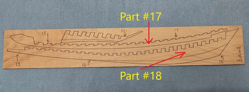
Seeing that we are busy with the Starboard side, I chose the appropriate drawing and this is what it looks like.

Part 17 and 18 - 副本Starboard.png

微信图片_20201212210407.jpg
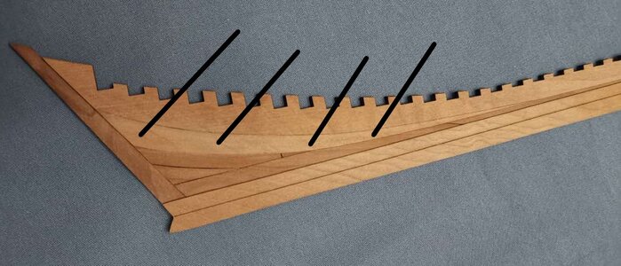
The actual sheet in wood. The side being shown above is obviously the Port Side.

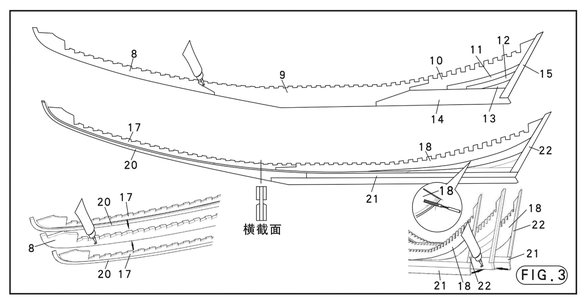
Our assembly drawing looks as follows:
Keel Assembly 1 - 副本 - 副本.png
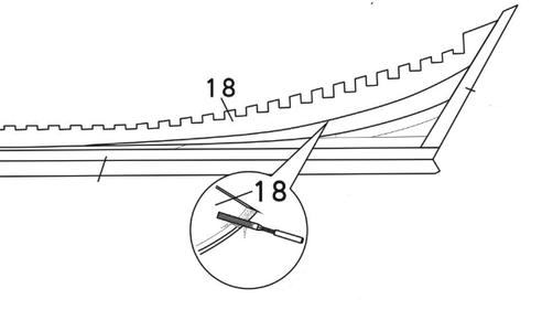
By now, you should all be very familiar with this drawing, BUT we need to zoom in ...
Bevelling.png
Here we can clearly see that Part # 18 needs to beveled up the indicated line before it is attached to the keel.
微信图片_20201212233210.jpg
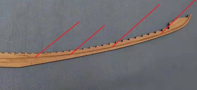
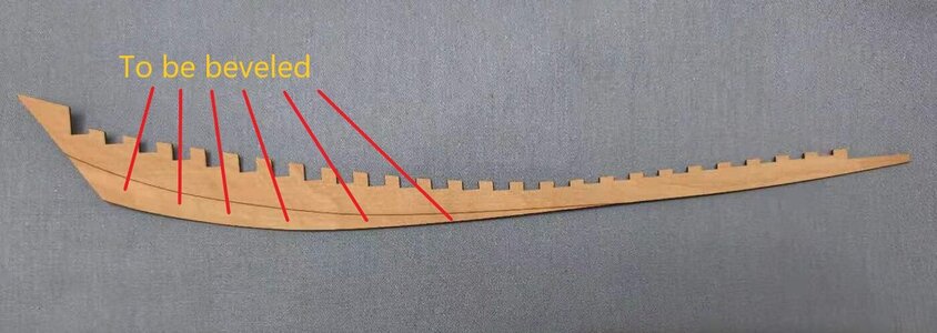
Part #18 removed from its sheet with the reference line clearly indicated. The red lines indicate the surface area that needs to be beveled.

The beveling in itself is not the tricky part. Here comes the challenge: Part #18 is 1mm thick and at the widest point the width measures 11mm! Can you imagine beveling an area of 11mm but the wood you have to work with is only 1mm thick? In theory that would mean that the part would be paper-thin at the bottom - in this case, theory and practice agreed totally. By the time I was finished, the sheet actually had a razor-like edge.:eek:

微信图片_20201214214508.jpg
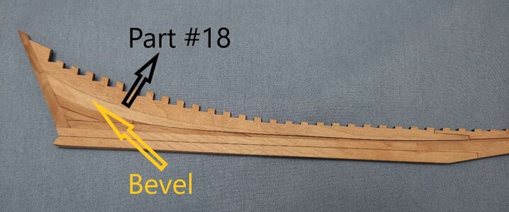
The beveled part glued in place. When gluing this part to the keel, make sure that you clamp the beveled portion really well to the keel and that leave it for the glue to dry properly. The piece fits beautifully into place - just look at the alignment with the sternpost! Remember Part #18 goes all the way to the top of the keel where it lines up with the notches so the fit is really extraordinary!
微信图片_20201214214450.jpg
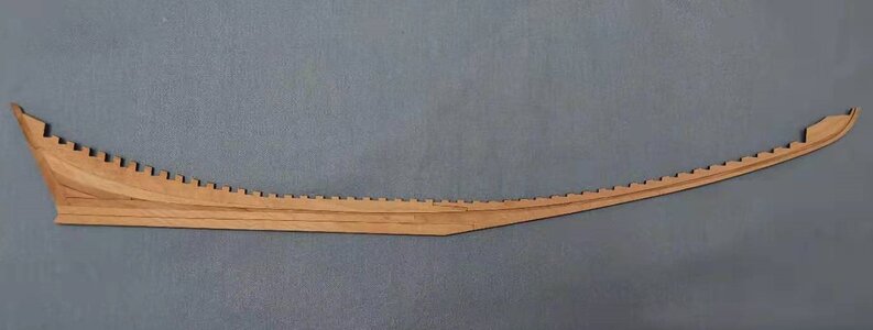
Here is the complete Part #18 attached to the inner keel.

TAADAAA!!!!
微信图片_20201214214459.jpg
I PRESENT one completed Starboard side keel.

Stay tuned!
 
@Kkonrath
@Peter Voogt

Hi Kurt and Peter. Seeing that you are asking the same question let me explain as the cross-section view is slightly misleading. First off: The Cross-Section is of Parts #20 and #17 - NOT #21. Remember Part #20 is the part that goes onto the bottom of the keel and that is indeed the part that gets beveled.

Build 44.jpg

This will explain the cross-section better:

Keel Assembly 1 - 副本 - 副本 (2).png

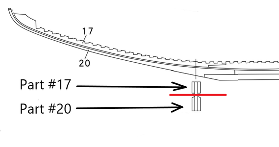
The indentation in the drawing (indicated by the red line) shows the orientation from Part #17 and Part #20 with reference to the inner keel when viewed from the front. It shows that Part #17 is absolutely square and requires no beveling. Part #20 shows the downward beveling as is indicated in the picture.
 
@Kkonrath
@Peter Voogt

Hi Kurt and Peter. Seeing that you are asking the same question let me explain as the cross-section view is slightly misleading. First off: The Cross-Section is of Parts #20 and #17 - NOT #21. Remember Part #20 is the part that goes onto the bottom of the keel and that is indeed the part that gets beveled.

View attachment 198784

This will explain the cross-section better:

View attachment 198795

The indentation in the drawing (indicated by the red line) shows the orientation from Part #17 and Part #20 with reference to the inner keel when viewed from the front. It shows that Part #17 is absolutely square and requires no beveling. Part #20 shows the downward beveling as is indicated in the picture.
What is misleading, is the fact they have a line thru the assy of the parts and a section view below it.
Normally a section view has section arrows through the area to be shown sectioned. And the section view will be labeled accordingly , ie Section A-A.
Here there is no section name or arrows, but a section below a line which makes one assume that the section is through that line.
In which case part 20 does not have a bevel through that section. Part 20 only has a bevel at the very end. And viewing that bevel in a view normal to the bevel, as you show, you would not see part 17.
So regardless, it is poor drafting practice and confusing at best. I would recommend they change that accordingly.
 
Last edited:
Hi Heinrich,

I'm fascinated by the joinery on this build. I keep on going back to look at your pictures of the steps you've completed and all I can say is "WOW"!!

Jan
Hello my friend. The joinery is incredible - unlike anything I have ever seen before. All credit for that goes to YuanQing - the accuracy of their laser cutting and the design.
 
YOU BET JAN WOW ON TOP OF WOW, NOW ONLY TO FIND OUT HOW I CAN COPY AND SAVE THIS THEN TO PDF IF POSSIBLE, HELP DAUGHTER, HELP SON-IN-LAW. GOD BLESS STAY SAFE YOU AND YOURS DON
Hello Don. As I have said to Jan - I would have loved to have been able to say that those are all my skills - but I have to give the credit to YuanQing!
 
Great build, I will learn a lot of things!
Kind regards,
Daniel
Daniel my friend it is great to have you here! Even though i do not comment on Steam Pinnace Janet, I still follow your progress religiously and I am very glad to hear that your physical condition has improved! Your Avatar of the Schnauzer is still my favourite. Each time I see it, it really makes me think of my - "now-no-longer-with-us" - Yorkshire Terrier, Rota.

微信图片_20201215084054.jpg

My big boy! :)
 
What is misleading, is the fact they have a line thru the assy of the parts and a section view below it.
Normally a section view has section arrows through the area to be shown sectioned. And the section view will be labeled accordingly , ie Section A-A.
Here there is no section name or arrows, but a section below a line which makes one assume that the section is through that line.
In which case part 20 does not have a bevel through that section. Part 20 only has a bevel at the very end. And viewing that bevel in a view normal to the bevel, as you show, you would not see part 17.
So regardless, it is poor drafting practice and confusing at best. I would recommend they change that accordingly.
Dean I have a conference call with YuanQing in an hour and will come back to you!
 
OK Gents, After the conference call the situation is very clear. Please read the instructions step-by-step.

1. The whole keel assembly is made up of THREE MAIN PARTS: An inner keel (Part #8) which is sandwiched between two outer keels. The outer keels are each made up out of four parts: Part #21 which is aligned at the BOTTOM of the keel from midships to the stern (rear); Part #20 which is aligned at the BOTTOM of the inner keel from midships towards the bow (front); Part #18 which is aligned at the TOP of the inner keel from midships to the stern (rear) and Part #17 which is aligned at the TOP of the keel from midships towards the bow (front).

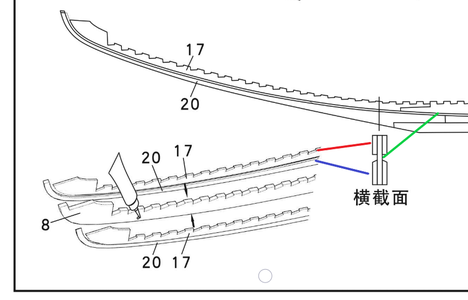
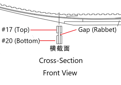
2. The cross-section deals only Parts #8 (the inner keel), Part #17 at the top and Part #20 at the bottom.

Keel Assembly 1 - 副本 - 副本 (3).png

The Chinese writing says: Cross-Section FRONT VIEW (which will be shown in the close-up drawing that will follow this.) @Dean62 Dean mentioned that the parts should have been marked - if you look at the drawing in the left lower-hand corner, you will see that it has been done. The red line indicates Part #17 at the top of the keel which is NOT beveled. Thus, it lies square with the inner keel as is shown at the top part of the cross-section.

The Blue line indicates Part #20 which is at the bottom of the keel and which has been beveled.

Build 45.jpg
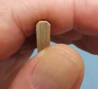
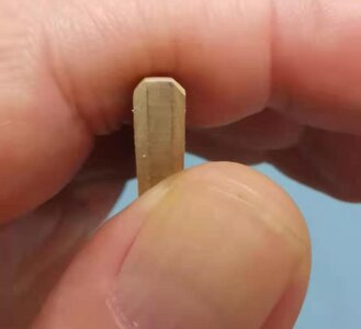
Here you can see the bevel on Part #20.

Keel Assembly 1 - 副本 - 副本 (3) - 副本.png

The close-up of the Cross-Section indicates Part #17 at the top and the beveled Part #20 at the bottom. The indentation between the two indicates the gap which will form the rabbet line.

Build 59.jpg

I trust this clears up all confusion.
 
Back
Top