YUANQING BLUENOSE - Heinrich

OK Gents, After the conference call the situation is very clear. Please read the instructions step-by-step.

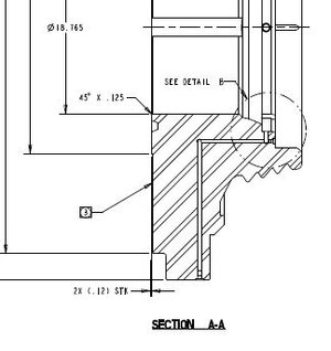
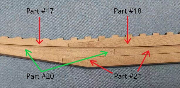
1. The whole keel assembly is made up of THREE MAIN PARTS: An inner keel (Part #8) which is sandwiched between two outer keels. The outer keels are each made up out of four parts: Part #21 which is aligned at the BOTTOM of the keel from midships to the stern (rear); Part #20 which is aligned at the BOTTOM of the inner keel from midships towards the bow (front); Part #18 which is aligned at the TOP of the inner keel from midships to the stern (rear) and Part #17 which is aligned at the TOP of the keel from midships towards the bow (front).

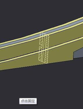
2. The cross-section deals only Parts #8 (the inner keel), Part #17 at the top and Part #20 at the bottom.

View attachment 198914

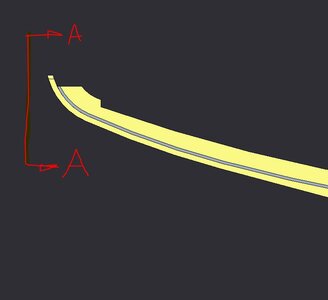
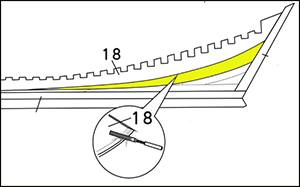
The Chinese writing says: Cross-Section FRONT VIEW (which will be shown in the close-up drawing that will follow this.) @Dean62 Dean mentioned that the parts should have been marked - if you look at the drawing in the left lower-hand corner, you will see that it has been done. The red line indicates Part #17 at the top of the keel which is NOT beveled. Thus, it lies square with the inner keel as is shown at the top part of the cross-section.

The Blue line indicates Part #20 which is at the bottom of the keel and which has been beveled.

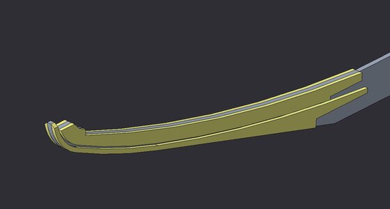
View attachment 198915
Here you can see the bevel on Part #20.

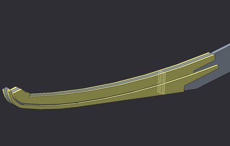
View attachment 198912

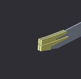
The close-up of the Cross-Section indicates Part #17 at the top and the beveled Part #20 at the bottom. The indentation between the two indicates the gap which will form the rabbet line.

View attachment 198916

I trust this clears up all confusion.
Sorry I’m still confused. But I do not have the kit or the instructions. I am only watching you build it. And you did not bevel part 20 on the top edge. You only beveled part 20 at the end or tip.
What am I missing? We’re you supposed to bevel the top of part 20 down the length of it?
And if so, why didn’t they mark a bevel line on it like they did on part 18?
 
Dean, if you look back at Post #85 that whole post explains it.

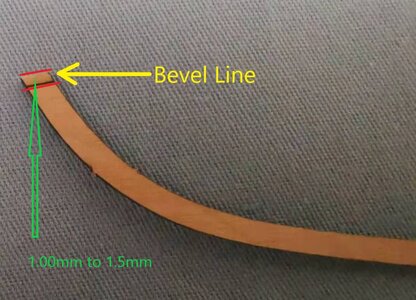
微信图片_20201211095741.jpg
There is the bevel line on Part #20 - only right at the end on the top. You can see that it is only the very tip that is bevelled.

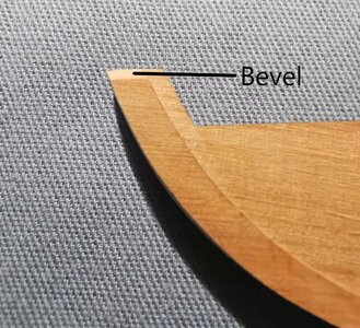
微信图片_20201212185903.jpg
The bevelled Part #20 - Side View

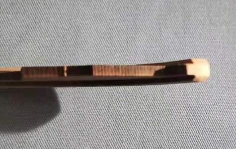
微信图片_20201212185933.jpg
Top View

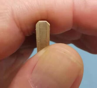
微信图片_20201212201041.jpg
Front View
 
@Dean62 You are one-hundred percent correct in that. At that particular point where the cross-section line is, Part #20 would not have been bevelled. That cross-section line should ideally have been at the tip, but then they could not illustrate the rabbet as that would have been hidden. That is why I attempt to illustrate with the pictures as well. As we all know - instructions rely on a combination of plans, pictures and descriptions and we go with whichever seems most clear at a particular point. For our members' sake, you can just follow this log. Before I do anything, I check with the test builder as well as afterwards. My build so far is 100% correct! :D Thumbsup
 
@Dean62 Hi Dean. I neglected to thank you for excellent questions - this is exactly what I would like to encourage in this log. If anyone I unsure or confused about anything, please say so and let us all contribute towards finding the answers. I reiterate - this is as new for me as it is for you guys, so we are all learning - I know I certainly am! :D
 
I work in 3d cad for a living doing Engineering, so this liberal use of views is most confusing to me! As it does not follow standard Engineering drawing practices!
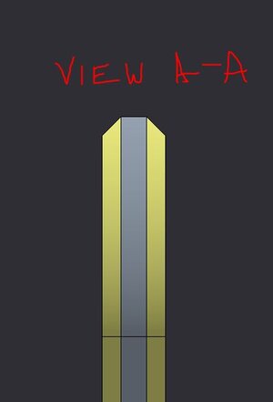
below is a quick model I threw together just as an example...
bn-01.JPGhere you see the pieces in color for reference, minus rib notches of course...just a crude example
bn-02.JPG
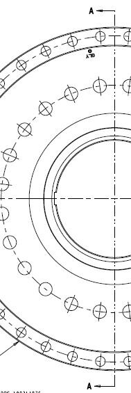
above I have shown the cross section in the approximate area they put the vertical line...
bn-03.JPG
above I have shown the part cut at the section...
bn-04.JPG
above I have shown view arrows that are normal to the bevel on part 20...
bn-05.JPG
above is what the appropriate view A-A would look like

In conclusion, they should not show an end or auxiliary view as a section view, this will always create confusion!!!
Section views should have section arrows where they are cut with the appropriate letter designation.
Auxiliary views should have view arrows with the appropriate letters for identification (like example above).
 
Absolutely, they should use standard engineering drawing practices on instructions or it becomes a free for all and subject to interpretation, which is never good. Just my two cents! ;)
Hello @Heinrich and @Dean62 (and all others),
I am in one line with Dean. Thats why I posted the same question with the snapshots. Dean was a step in front of me with the complementary questions. And posted nice exempels.
By the crime-scene investigation we worked with the same drawing principals. In cord there will be no space for wrong interpretations. Therefor my confusion by the little cross-view picture.
The nice bevel of part 18 is clear. A mis-interpretation of me. A little tip: give the aria to beveled a color.
1608021236639.png
So, no bevel on top of part 20 over its overall lengt. (Otherwise on top of part 20, 2 bevels would come together.)

PS to Heinrich:
This is not a cord! Building together is the most beautifull build there is!
I realy realy realy appreciate your contributions to this build-log. It will take a lot of your time! And it saved us a lot of time! It becomes a top-manual.

Regards, Peter
 
Last edited:
@Dean62
@Peter Voogt

Guys - that is absolutely the way that I want it! Thumbsup It is absolutely wonderful - Dean's drawings add SO much to the log and therefore the questions that are asked and the queries raised are imperative. This is already the #1 Thread on SOS and now everybody can see why. I have said from the start that we are a family with the common goal of making sure that we all have a wonderful time building Bluenose. Contributions like these add to the overall participation in and understanding of the build. Keep it coming!
@Heinrich
Glad we can clear it up, so everyone will know what is needed on part 20!
The instructions should omit the bevel on part 20 in the section view, to show the rabbet. There should be an auxiliary view added to show the bevel on part 20, as I have shown above. It is basically an end view, where the bevel is normal to the view.
They tried to show two different views in one view, which is where the confusion was created. And finally they should use section and view arrows, and label views accordingly, ie. view A-A, section B-B, etc.
Using standard Engineering drawing practice on the instructions, should ensure they are understood correctly by all. Just my two cents. ;)
 
Last edited:
@Dean62 The info and suggestions have been forwarded to YuanQing who is also very appreciative of your suggestions.

微信图片_20201216083056.jpg

They particularly like this one which - as you can see - has already been tagged and forwarded to the drawing department. They are also in full agreement with the suggestion of a separate front view illustration.
 
@Heinrich
Glad we can clear it up, so everyone will know what is needed on part 20!
The instructions should omit the bevel on part 20 in the section view, to show the rabbet. There should be an auxiliary view added to show the bevel on part 20, as I have shown above. It is basically an end view, where the bevel is normal to the view.
They tried to show two different views in one view, which is where the confusion was created. And finally they should use section and view arrows, and label views accordingly, ie. view A-A, section B-B, etc.
Using standard Engineering drawing practice on the instructions, should ensure they are understood correctly by all. Just my two cents. ;)
For my much later building of these parts it would be very helpful for a properly drawn section view and clarification tapering shaded area be shown in elevation as suggested in the format of a pdf that we can download and print out to attach to the drawings. My older brain will not retain these verbal corrections. I am a visual and hands on practice learner. Thanks for someone generating a pdf downloadable annotated drawing. Rich (PT-2) Retired architect who is also very familiar with the section arrows direction of view drafting format.
 
@Dean62 The info and suggestions have been forwarded to YuanQing who is also very appreciative of your suggestions.

View attachment 199124

They particularly like this one which - as you can see - has already been tagged and forwarded to the drawing department. They are also in full agreement with the suggestion of a separate front view illustration.
@Heinrich
This is exciting news! The fact that we have influence, is invaluable! I am so glad they are willing to listen and make any necessary corrections to ensure a successful build by future modelers. Like me... ;)
 
@Heinrich
This is exciting news! The fact that we have influence, is invaluable! I am so glad they are willing to listen and make any necessary corrections to ensure a successful build by future modelers. Like me... ;)
A thought on this is that it takes all of the crew pulling their oars together that propels us forward. Rich (PT-2)
 
Hello Everyone

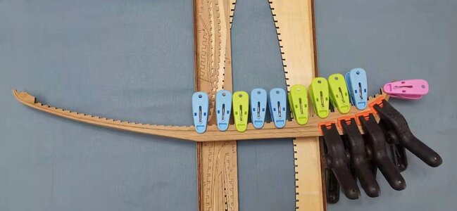
Work continued today in the Nantong Shipyard. With the Starboard side of the keel finished, it was now time to focus on the Port Side. Part #17 was glued to the inner keel from midships to the bow and then it was the turn again of that pesky Part #18 that goes at the top from midships to the stern. In my previous post I cautioned you guys to be careful with this. Work slowly and at very little of an angle. I used a little diamond file which probably looks more like a toy than a tool, but which, nevertheless, got the job done. I would file a little and walk away to rest my eyes - then back at it again. This piece is wafer thin once beveled - concentrate and execute caution!

微信图片_20201216131852.jpg
When gluing Part #18 to the inner keel, make sure that it is clamped properly. Because the piece is so thin once beveled, the beveled part will not lie completely flat against the keel - that is what the four big, black clamps were used for. The fitment at the top of the keel is no issue - just make sure that all notches are properly aligned and that the rearmost part is aligned perfectly with the sternpost.

微信图片_20201216172357.jpg
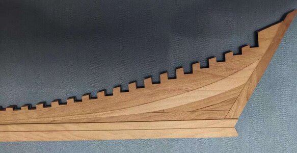
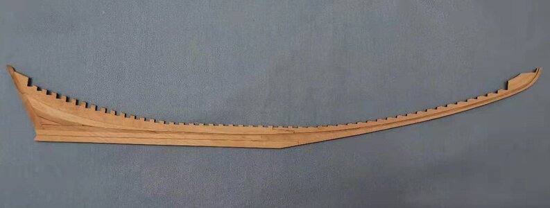
Done correctly, this is what she should look like. ROTF ExplosionBottle That's how I felt when Part #18 was finally installed and when the end result looked like that. The lighter wood colour indicates the section of Part #18 that has been beveled. The accuracy of the laser-cutting is UNBELIEVABLE and the grain in that wood ... !
微信图片_20201216172403.jpg
This picture shows the midships section where all keel parts join. I have coloured Part #20 green for the picture because even with a macro-closeup, the joint line between Parts #20 and @21 is almost invisible. With the naked eye is well nigh invisible.

So let's see next how our keel stacks up against that of the YuanQing test builder.

微信图片_20201216143111.jpg
YuanQing - Starboard Side

Build 59.jpg
SOS Starboard Side

微信图片_20201216143117.jpg
YuanQing Port Side

微信图片_20201216181915.jpg
SOS Port Side

And with that, we have come to the end of the keel assembly! And next? Yep ... you guessed it ... FRAMES! :eek:

But first, it's back to the administrative office of Bluenose to send PM's to the next two clients who will receive PayPal Bills tomorrow. Wonder who they are ...

微信图片_20201216160733.jpg
 
Back
Top