Absolutely love the Floydian language...Keep it on.  ...but don't sit down, it's time to dig another one
-

Win a Free Custom Engraved Brass Coin!!!
As a way to introduce our brass coins to the community, we will raffle off a free coin during the month of August. Follow link ABOVE for instructions for entering.
-

PRE-ORDER SHIPS IN SCALE TODAY!
The beloved Ships in Scale Magazine is back and charting a new course for 2026!
Discover new skills, new techniques, and new inspirations in every issue.
NOTE THAT OUR FIRST ISSUE WILL BE JAN/FEB 2026
- Home
- Forums
- Ships of Scale Group Builds and Projects
- Bluenose PoF Group Build
- Bluenose Group Build Logs
You are using an out of date browser. It may not display this or other websites correctly.
You should upgrade or use an alternative browser.
You should upgrade or use an alternative browser.
YUANQING BLUENOSE - Peter Voogt [COMPLETED BUILD]
- Thread starter Peter Voogt
- Start date
- Watchers 74
The 2 bearing beams for the front/between floor are also included. They are not that big and run over frames 4 to 12. But no less laborious for that. You are working with your big hands in the bow.
The trick with applying the markings and aligning with the large skewers didn't work here. The 2 beams are right next to each other and every small unevenness is immediately punished. Made 2 attempts to get them aligned.
But the advantage of looking ahead in the manual also brought a solution.
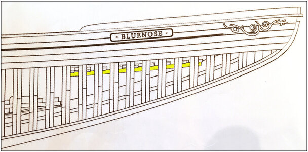
The drawing shows that these small bearing beams run parallel to the deck and skin planks. And so to the bearing beams of that deck.
That's why I have made 3 planks at the right size between both bearing beams: For the beginning, halfway and the end:
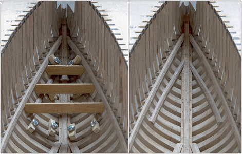
Pushed the 2 bearing beams into place in such a way that the 3 planks got stuck under the top bearing beams and then everything with the clamps fastened to dry.
With the result next to it.
And this photo from the side shows the comparison with the drawing:
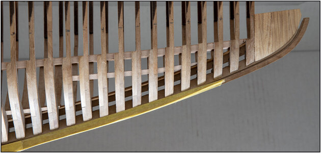
For me these 2 beams are now called “Little Basterds”. It bought the necessary time and energy to get them neatly in place.
The YQ tutorial now continues with the 2 planks next to the keelson. But that's where I made the sisters keelson for. Then the nest step would be the floor beams for the lower decks.
But the aforementioned Saga also shows 2 bearing beams in the rear of the hull. I'm going to make them scratch from remnants of the sheets from which the keel parts come out. That has the desired thickness and I think I can saw the right length for these 2 beams.
So to be continued.
Regards, Peter
The trick with applying the markings and aligning with the large skewers didn't work here. The 2 beams are right next to each other and every small unevenness is immediately punished. Made 2 attempts to get them aligned.
But the advantage of looking ahead in the manual also brought a solution.

The drawing shows that these small bearing beams run parallel to the deck and skin planks. And so to the bearing beams of that deck.
That's why I have made 3 planks at the right size between both bearing beams: For the beginning, halfway and the end:

Pushed the 2 bearing beams into place in such a way that the 3 planks got stuck under the top bearing beams and then everything with the clamps fastened to dry.
With the result next to it.
And this photo from the side shows the comparison with the drawing:

For me these 2 beams are now called “Little Basterds”. It bought the necessary time and energy to get them neatly in place.
The YQ tutorial now continues with the 2 planks next to the keelson. But that's where I made the sisters keelson for. Then the nest step would be the floor beams for the lower decks.
But the aforementioned Saga also shows 2 bearing beams in the rear of the hull. I'm going to make them scratch from remnants of the sheets from which the keel parts come out. That has the desired thickness and I think I can saw the right length for these 2 beams.
So to be continued.
Regards, Peter
Last edited:
I admire your careful and precise work. A thing to behold! RichThe 2 bearing beams for the front/between floor are also included. They are not that big and run over frames 4 to 12. But no less laborious for that. You are working with your big hands in the bow.
The trick with applying the markings and aligning with the large skewers didn't work here. The 2 beams are right next to each other and every small unevenness is immediately punished. Made 2 attempts to get them aligned.
But the advantage of looking ahead in the manual also brought a solution.
View attachment 242232
The drawing shows that these small bearing beams run parallel to the deck and skin planks. And so to the bearing beams of that deck.
That's why I have made 3 planks at the right size between both bearing beams: For the beginning, halfway and the end:
View attachment 242233
Pushed the 2 bearing beams into place in such a way that the 3 planks got stuck under the top bearing beams and then everything with the clamps fastened to dry.
With the result next to it.
And this photo from the side shows the comparison with the drawing:
View attachment 242234
For me these 2 beams are now called “Little Basterds”. It bought the necessary time and energy to get them neatly in place.
The YQ tutorial now continues with the 2 planks next to the keelson. But that's where I made the sisters keelson for. Then the nest step would be the floor beams for the lower decks.
But the aforementioned Saga also shows 2 bearing beams in the rear of the hull. I'm going to make them scratch from remnants of the sheets from which the keel parts come out. That has the desired thickness and I think I can saw the right length for these 2 beams.
So to be continued.
Regards, Peter
Thanxs Rich, I try to keep the bow at the right tension. To keep the level.I admire your careful and precise work. A thing to behold! Rich
But not Stretched to the point of no turning back.
Regards, Peter
The last 2 beams.
As I wrote in the previous post, I came across these 2 beams in the book “Bluenose II, Saga of the Great Fishing Schooners” by L.B. Jenson.
On pg. 40 are these drawings, so with the above source reference and purely to illustrate the build of my model:
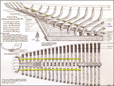
They call these beams "Stringers". I accentuated them in both drawings.
These are of course drawings of the BN-II. But it is mentioned that the main construction has been taken over almost completely from the original BN and that the interior in particular is partly different.
I think those rear beams also make sense, because now the hull has 3 longitudinal reinforcements over the full length:
1-below:
- the keel;
2 middle:
- the front/between floor bearing beams over the frames 4 – 12;
- the under floor bearing beams over the frames 13 – 43;
- the rear floor springers over the frames 41 – 57;
3-upper:
- the front deck bearing beams over the frames 1 – 27;
- the aft deck bearing beams over the frames 27 – 57.
From the scrap wood of the sheet from which the keel parts came, I was able to saw a few strips of 2.7 mm / 0.106”.
The Saga stated in the drawing in the stringers:
“Stringers: 3 ft off centre, extends to first square frame”.
The drawing shows them running over the aft 16 frames.
3 ft = 91.44 cm and in 1:72 it is 12.7 mm / 0.5”.
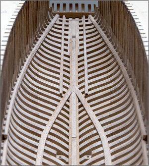
In the model, they come at the stern to lie in the longitudinal direction exactly between the keel and the top bearing beams. And to the front connect exactly against the 1st floor beam of the under floor.
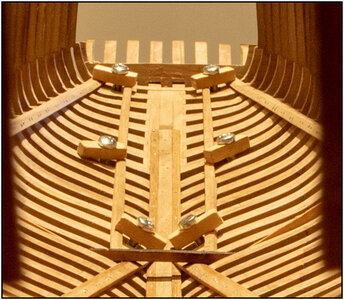
I clamped the 1st floor beam in place for a while, so I could make the 2 beams neatly to size. With a little bevel on the outside, because there will (probably) also be a piece of floor on or between.
Nail holes marked, holes drilled, beams glued, clamped and let dry, nails put ....
Resulting in:
To conclude this chapter about these inner reinforcement, some overall picture:
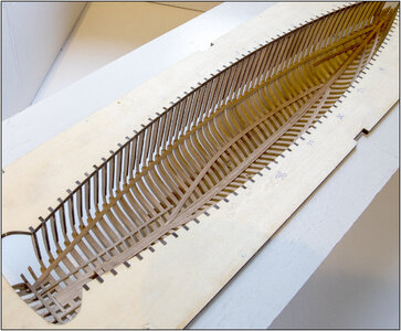
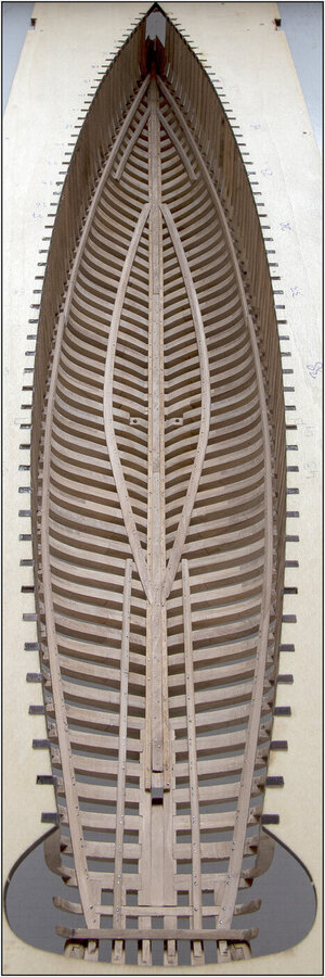

Regards, Peter
As I wrote in the previous post, I came across these 2 beams in the book “Bluenose II, Saga of the Great Fishing Schooners” by L.B. Jenson.
On pg. 40 are these drawings, so with the above source reference and purely to illustrate the build of my model:

They call these beams "Stringers". I accentuated them in both drawings.
These are of course drawings of the BN-II. But it is mentioned that the main construction has been taken over almost completely from the original BN and that the interior in particular is partly different.
I think those rear beams also make sense, because now the hull has 3 longitudinal reinforcements over the full length:
1-below:
- the keel;
2 middle:
- the front/between floor bearing beams over the frames 4 – 12;
- the under floor bearing beams over the frames 13 – 43;
- the rear floor springers over the frames 41 – 57;
3-upper:
- the front deck bearing beams over the frames 1 – 27;
- the aft deck bearing beams over the frames 27 – 57.
From the scrap wood of the sheet from which the keel parts came, I was able to saw a few strips of 2.7 mm / 0.106”.
The Saga stated in the drawing in the stringers:
“Stringers: 3 ft off centre, extends to first square frame”.
The drawing shows them running over the aft 16 frames.
3 ft = 91.44 cm and in 1:72 it is 12.7 mm / 0.5”.
In the model, they come at the stern to lie in the longitudinal direction exactly between the keel and the top bearing beams. And to the front connect exactly against the 1st floor beam of the under floor.

I clamped the 1st floor beam in place for a while, so I could make the 2 beams neatly to size. With a little bevel on the outside, because there will (probably) also be a piece of floor on or between.
Nail holes marked, holes drilled, beams glued, clamped and let dry, nails put ....
Resulting in:

To conclude this chapter about these inner reinforcement, some overall picture:


Regards, Peter
Last edited:
I wondered about that. Same with decking. I used strips to install 1/2 decking on not just the lower beams, but also on the forward deck beams. Just because.The last 2 beams.
As I wrote in the previous post, I came across these 2 beams in the book “Bluenose II, Saga of the Great Fishing Schooners” by L.B. Jenson.
On pg. 40 are these drawings, so with the above source reference and purely to illustrate the build of my model:
View attachment 242357
They call these beams "Stringers". I accentuated them in both drawings.
These are of course drawings of the BN-II. But it is mentioned that the main construction has been taken over almost completely from the original BN and that the interior in particular is partly different.
I think those rear beams also make sense, because now the hull has 3 longitudinal reinforcements over the full length:
1-below:
- the keel;
2 middle:
- the front/between floor bearing beams over the frames 4 – 12;
- the under floor bearing beams over the frames 13 – 43;
- the rear floor springers over the frames 41 – 57;
3-upper:
- the front deck bearing beams over the frames 1 – 27;
- the aft deck bearing beams over the frames 27 – 57.
From the scrap wood of the sheet from which the keel parts came, I was able to saw a few strips of 2.7 mm / 0.106”.
The Saga stated in the drawing in the stringers:
“Stringers: 3 ft off centre, extends to first square frame”.
The drawing shows them running over the aft 16 frames.
3 ft = 91.44 cm and in 1:72 it is 12.7 mm / 0.5”.
In the model, they come at the stern to lie in the longitudinal direction exactly between the keel and the top bearing beams. And to the front connect exactly against the 1st floor beam of the under floor.
View attachment 242358
I clamped the 1st floor beam in place for a while, so I could make the 2 beams neatly to size. With a little bevel on the outside, because there will (probably) also be a piece of floor on or between.
Nail holes marked, holes drilled, beams glued, clamped and let dry, nails put ....
Resulting in:
View attachment 242359
To conclude this chapter about these inner reinforcement, some overall picture:
View attachment 242360
View attachment 242361
View attachment 242362
Regards, Peter
Your work looks great.
Thanxs for the reply, EJ.I wondered about that. Same with decking. I used strips to install 1/2 decking on not just the lower beams, but also on the forward deck beams. Just because.
Your work looks great.
The text in the post was perhaps 'a little bit' long. Where are you wondering about?
My BN will also be 1/2 planked on the floors and walls, on the port side. Of course with AL-FI
Regards, Peter
The wondering was about - were there more decks below the main deck, etc. Just thinking out loud. Obviously, there were more decked levels below the main deck as your research has shown.Thanxs for the reply, EJ.
The text in the post was perhaps 'a little bit' long. Where are you wondering about?
My BN will also be 1/2 planked on the floors and walls, on the port side. Of course with AL-FI.
Regards, Peter
I also thought - gosh, if there were deck beams (as supplied in the bow area) , why was there no decking provided? So - I decked the port side of both the lowest deck and the forward deck, just because I thought it looked correct. I also thought about bulkheads and the inner side of the frames being planked, but decided against going down that rabbit hole.
Apparently, great minds think alike.
There was a deck at the stern for the cabin, a ladder going down to it from the cabin doors…a lot of details were left out, it is just basic framing provided. So…up to the builder how much research and additional detail.The wondering was about - were there more decks below the main deck, etc. Just thinking out loud. Obviously, there were more decked levels below the main deck as your research has shown.
I also thought - gosh, if there were deck beams (as supplied in the bow area) , why was there no decking provided? So - I decked the port side of both the lowest deck and the forward deck, just because I thought it looked correct. I also thought about bulkheads and the inner side of the frames being planked, but decided against going down that rabbit hole.
Apparently, great minds think alike.
- Joined
- Oct 28, 2018
- Messages
- 760
- Points
- 403

Have n't been here for a few days, nice progression with nice pictures.
I see on the Dutch Forum that your work is highly appreciated.
Rightly so
I see on the Dutch Forum that your work is highly appreciated.
Rightly so
- Joined
- Oct 28, 2018
- Messages
- 760
- Points
- 403

Peter,
Read your post Read your post #442
With today's knowledge, wouldn't it have been easier to apply this earlier?
I read Donnie's post, with Heinrich's response to this, that the logic in China is different from our European standards, it reminded me when I read post #442
Read your post Read your post #442
With today's knowledge, wouldn't it have been easier to apply this earlier?
I read Donnie's post, with Heinrich's response to this, that the logic in China is different from our European standards, it reminded me when I read post #442
Aha EJ, now I understand. You are correct: when there is a deck of deck beams, then it can be decked.The wondering was about - were there more decks below the main deck, etc. Just thinking out loud. Obviously, there were more decked levels below the main deck as your research has shown.
I also thought - gosh, if there were deck beams (as supplied in the bow area) , why was there no decking provided? So - I decked the port side of both the lowest deck and the forward deck, just because I thought it looked correct. I also thought about bulkheads and the inner side of the frames being planked, but decided against going down that rabbit hole.
Apparently, great minds think alike.
Every week or month I found more information about the BN. Luckely I am not going fast
Regards, Peter
You are correct Dean.There was a deck at the stern for the cabin, a ladder going down to it from the cabin doors…a lot of details were left out, it is just basic framing provided. So…up to the builder how much research and additional detail.
In The Saga there are drawings of different cabins. In the rear for the Captain, it appears on the starboard side. But also some others for some crew members.
On a drawing you see the stairs and in the door opnening you got a glimp of the Steering Wheel. But it is a impression of the schooner ‘Caroline Rose’. AL-FI will help me with the disign of the inside.
Regards, Peter
Hi Henk,Have n't been here for a few days, nice progression with nice pictures.
I see on the Dutch Forum that your work is highly appreciated.
Rightly so
On the Dutch forum it is only you and me who are building the BN. There it is a ‘kind of special’.
Her on the SoS we have now 18 build-log, with 40 (open registered) shiped.
But (luckely) all the builds are different
I do not think so, IMHO. The upper bearing beams were longer and easier to align. I could now nicely align this smaller on those longer beams. With the help of my own made spacers. The fact that they run parallel to each other is not described in the manual. You can only see it in the drawings. Only that you have to apply them on the marking lines, if they still exist after sanding.Peter,
Read your post Read your post #442
With today's knowledge, wouldn't it have been easier to apply this earlier?
I read Donnie's post, with Heinrich's response to this, that the logic in China is different from our European standards, it reminded me when I read post #442
About ‘different logic’: A developer thinks differently about a manual than a builder/user. I experienced this myself when a company was building an complex application for my work department (CSI Analyses). What they has written
 .... Then I sat down next to those builders and I translated their input into what makes sense for the user.
Regards, Peter
Last edited:
- Joined
- Jan 9, 2020
- Messages
- 10,566
- Points
- 938

Great comments and inputs guys. @Henk Liebre Henk, I don't know if it is case of a different logic - it is just that I think they attach far less importance to the instructions. And the reason for that is the dedicated pages that each model manufacturer has - very much the same as what we have here in the group build. The big difference is that a company like Unicorn, for instance, has 120 000 plus followers on their dedicated page - so you can imagine the wealth of information that is at hand to everyone.
Thanks Heinrich, for this understanding reply.Great comments and inputs guys. @Henk Liebre Henk, I don't know if it is case of a different logic - it is just that I think they attach far less importance to the instructions. And the reason for that is the dedicated pages that each model manufacturer has - very much the same as what we have here in the group build. The big difference is that a company like Unicorn, for instance, has 120 000 plus followers on their dedicated page - so you can imagine the wealth of information that is at hand to everyone.
Just a question that now arises: does YQ have its own website?
Searching the web I found nothing.
Regards, Peter
- Joined
- Jan 9, 2020
- Messages
- 10,566
- Points
- 938

Hoi Peter. None of the Chinese manufacturers (the only exception is CAF as far as I know) has a website. All the marketing gets done directly on Taobao and Jidong. Websites are old news in China - no one uses them anymore.
Haha, good thing we use this old-boys-networkHoi Peter. None of the Chinese manufacturers (the only exception is CAF as far as I know) has a website. All the marketing gets done directly on Taobao and Jidong. Websites are old news in China - no one uses them anymore.
We have to keep in mind that Saga is primarily about BN II. As far as I have been able to ascertain there are NO drawings about the compartmentation below the deck on the actual BN, only some descriptions that don't help a builder; even the statement that for the Chicago World Fair "the fish holds were removed . . . and quarters on one side built and displays on the other (I don't have that page in front of me right now). RichYou are correct Dean.
In The Saga there are drawings of different cabins. In the rear for the Captain, it appears on the starboard side. But also some others for some crew members.
On a drawing you see the stairs and in the door opnening you got a glimp of the Steering Wheel. But it is a impression of the schooner ‘Caroline Rose’. AL-FI will help me with the disign of the inside.
Regards, Peter
Thanxs for the info, Rich.We have to keep in mind that Saga is primarily about BN II. As far as I have been able to ascertain there are NO drawings about the compartmentation below the deck on the actual BN, only some descriptions that don't help a builder; even the statement that for the Chicago World Fair "the fish holds were removed . . . and quarters on one side built and displays on the other (I don't have that page in front of me right now). Rich
So, nothing is (officially) known of the inside.
So, nothing is (officially) wrong if I build ‘something’ of the inside. With the help of AL-FI.
Regards, Peter


