You are now the reincarnation of Capt Walters telling the ship yard what and where he wanted things below decks and Wm. Roue was not concerned with those matters as long as the holds could contain the fish "ballast" harvest that he had designed her to carry for her trim. The matter for you is in your own mind and hands. RichThanxs for the info, Rich.
So, nothing is (officially) known of the inside.
So, nothing is (officially) wrong if I build ‘something’ of the inside. With the help of AL-FI.
Regards, Peter
-

Win a Free Custom Engraved Brass Coin!!!
As a way to introduce our brass coins to the community, we will raffle off a free coin during the month of August. Follow link ABOVE for instructions for entering.
-

PRE-ORDER SHIPS IN SCALE TODAY!
The beloved Ships in Scale Magazine is back and charting a new course for 2026!
Discover new skills, new techniques, and new inspirations in every issue.
NOTE THAT OUR FIRST ISSUE WILL BE JAN/FEB 2026
- Home
- Forums
- Ships of Scale Group Builds and Projects
- Bluenose PoF Group Build
- Bluenose Group Build Logs
You are using an out of date browser. It may not display this or other websites correctly.
You should upgrade or use an alternative browser.
You should upgrade or use an alternative browser.
YUANQING BLUENOSE - Peter Voogt [COMPLETED BUILD]
- Thread starter Peter Voogt
- Start date
- Watchers 74
Thanxs Rich.You are now the reincarnation of Capt Walters telling the ship yard what and where he wanted things below decks and Wm. Roue was not concerned with those matters as long as the holds could contain the fish "ballast" harvest that he had designed her to carry for her trim. The matter for you is in your own mind and hands. Rich
Are the dimensions and location of the fish holds known? In the middle on the Lowes floor looks logical.
Or is it the story: ‘You may change everything but not the fish holds’.
Regards, Peter
Interesting question, Heinrich.I wonder if shipbuilding had a "White Book" like the FIA has with regards to specifications, rules and scrutineering guidelines.
In Howard Chapelle's book I found: [Start quoting]:
The racing of fishing schooners, prior to the Canadian 'international' challenge in 1920, had not produced vessels especially designed to race. All contenders were out-and-out fishing schooners, whose owners, or skippers, or backers, thought them fast and would foot the costs of fitting out. In such informal races as these there were no measurement limitations of rules; it was boat-for-boat, in which the larger fishing schooners usually won easily, as would be expected. But formal racing, as required by the Canadian challenge, led to a "deed of gift" and to measurements limitations that would determine a vessel's eligibility to race." [And quote].
So, the BN of 1921 fell in this new period.
On the internet I found in 1923 there where new ruls.
But I have not found "the ruls" yet.
Regards, Peter
And after some search, in this document on the page:
-> Artikel with the rules <-
[Start quoting]:
W. J. Roue, a young naval architect, was selected to design such a fishing schooner to try to restore some of the badly eroded Canadian pride. A sleek looking craft, designed to meet the race rule specifications of 145 feet overall maximum length and racing trim water line length not exceeding 112 feet, was constructed at the Smith and Rhuland Yard in Lunenburg, Nova Scotia.[End quoting]
regards, Peter
There are no dimensions that I have found or in replies to my inquires sent out.Thanxs Rich.
Are the dimensions and location of the fish holds known? In the middle on the Lowes floor looks logical.
Or is it the story: ‘You may change everything but not the fish holds’.
Regards, Peter
If you do some "fishing around" you may be able to make a rough conversion of the largest known return back to Lunenberg and conert that into some volume within the ceiling of the hull but it would be a rough estimate as it includes both fish and salt along with the packing density within the fore/aft hull part that the calculus would be applied. Sorry, Rich
Don’t be sorry, Rich.There are no dimensions that I have found or in replies to my inquires sent out.
If you do some "fishing around" you may be able to make a rough conversion of the largest known return back to Lunenberg and conert that into some volume within the ceiling of the hull but it would be a rough estimate as it includes both fish and salt along with the packing density within the fore/aft hull part that the calculus would be applied. Sorry, Rich
When there is nothing, we won’t find it. But sometimes it’s hidden in the depths of the internet and (still) hidden in some archive. Or old-fashioned analog in a book.
And then one day - hooray! Another way for gnomes to say Hoooooooooray.
Regards, Peter
At least this is in the class of "We know what we do not know." The real revelations for the future are the "We don't know what we don't know" and those will open new harbors. Rich@PT-2 And think of it this way - the next generation of Bluenose builders (the model) will all be able to source the wonderful resources and research that this group of builders have created for them!
Mwwwww ....... hopefully for the new model builders. Working the last years before retirement, there was a younger generation with the adage; ‘We don’t know what we don’t know, we know (everything)’. And did you have the guts to explain something ..........At least this is in the class of "We know what we do not know." The real revelations for the future are the "We don't know what we don't know" and those will open new harbors. Rich
But now I feel like a grumpy old man ...... back to modelbuilding.
Regards, Peter
With some back tracking into Saga there are two drawings on pp 66, 67, without any scale but enough shown for bulkheads when compared with the deck furniture above to make bulkhead placements for 1921 and 1935 if we Believe the titles.Mwwwww ....... hopefully for the new model builders. Working the last years before retirement, there was a younger generation with the adage; ‘We don’t know what we don’t know, we know (everything)’. And did you have the guts to explain something ..........
But now I feel like a grumpy old man ...... back to modelbuilding.
Regards, Peter
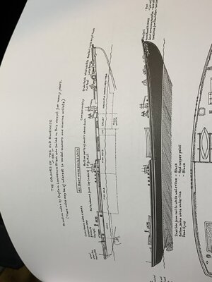
Now 1921 which is miss-titled above
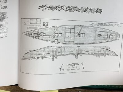 from p 66 You will have to flip it 180 degrees to get the proper view.
Rich
Browsed through the Saga so many times and never seen it. Analog hidden.With some back tracking into Saga there are two drawings on pp 66, 67, without any scale but enough shown for bulkheads when compared with the deck furniture above to make bulkhead placements for 1921 and 1935 if we Believe the titles. View attachment 243213
Now 1921 which is miss-titled aboveView attachment 243215 from p 66 You will have to flip it 180 degrees to get the proper view.
Rich
Thanks, Rich, for keeping me Sharp.
Regards, Peter
Last edited:
Now that the Duc is ready, I can now fully focus on the BN.
First I looked at what I'm going to tackle in the near future.
Decided to sand the outside of the hull first. Then I don't have any dust in nooks and crannies when applying the 1st layer, lacquer or oil.
Got to work in the garden, with the method that I also used on the inside:
accentuate all trusses with a pencil, sand, feel with the thin balsa strip, mark again, sand, feel etc etc etc.:
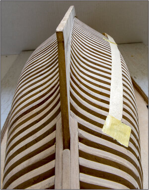
The balsa strip and the macro photos are not forgiving. But it will be tight.
After a few hours, this BlueWhale as a result:
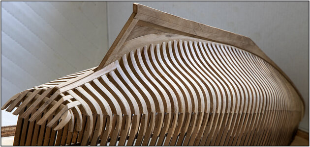
The noses of the frames, at the connection to the keel, receive some extra attention.
And then ........ the Garboard Strake slide neatly in the rabbet:
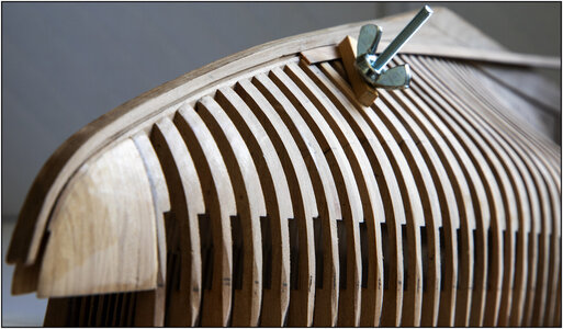
Because now the theory, which I have articulated in my post #47, and the practice comes together.
The frames fits nicely and flows over to the bevel on the top of the rabbet.
Regards, Peter
First I looked at what I'm going to tackle in the near future.
Decided to sand the outside of the hull first. Then I don't have any dust in nooks and crannies when applying the 1st layer, lacquer or oil.
Got to work in the garden, with the method that I also used on the inside:
accentuate all trusses with a pencil, sand, feel with the thin balsa strip, mark again, sand, feel etc etc etc.:

The balsa strip and the macro photos are not forgiving. But it will be tight.
After a few hours, this BlueWhale as a result:

The noses of the frames, at the connection to the keel, receive some extra attention.
And then ........ the Garboard Strake slide neatly in the rabbet:

Because now the theory, which I have articulated in my post #47, and the practice comes together.
The frames fits nicely and flows over to the bevel on the top of the rabbet.
Regards, Peter
Thanks Heinrich. That's also where I was thinking about. Old memmories.I said that on the Dutch site that it is wonderful when theory and practice come together. Was it not Hannibal of the A-Team who said :"I just love it when a plan comes together!" Welgedaan, Peter!
There is more 'thinking and planning' ...... see below.
Rergards, Peter
Last edited:
In order to determine where I can or cannot reach with the 1st layer of paint or oil, I am further thinking about the deck beams.
In my post #372 I already explained that I am not going to let the top deck beams end between the frames, but rather shorten and 'lock' them between the 'Clamps', as shown in The Saga.
Nothing is shown for the beams in the lower floors. With the exception for partly the small beams between the 'Stringers', see my post #445.
To view what I mean: In the YQ manual, the beams are placed in front of the frames and extend between the frames:
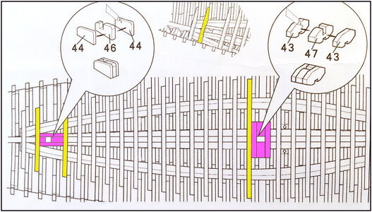
I highlighted them in yellow. (Blue is coming soon )
)
But this seems not logical to me, because how do they get the beams attached to the frames at the ends? There is almost no space for hammering between the frames.
But in this detailed account of the construction of the model by G. Bodnar using the drawings of P.F. Eisnor,
(see link: http://www.modelshipbuilder.com/page.php?26)
you can see he placed the beams on the frames:
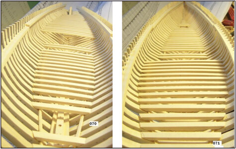
Here I have placed 2 beams in the hull to show the difference:
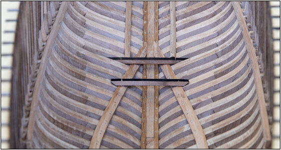
The front should of course still have the correct chamfer.
Thanks to the photo I can still see some pencil lines. Occasional shot of the frames while accentuating before sanding
If I move the beams to on the frames, that means that everything shifts 4.5 mm / 0,177” backwards. So also all blocks, with recesses, between the beams.
I made it blue in the photo of the YQ manual (see above).
Not a problem, because at the front of both blocks I can remove 4.5 mm.
At the raised lower deck at the front I have to see what can and cannot be done there. Because there are more blocks placed between the beams:
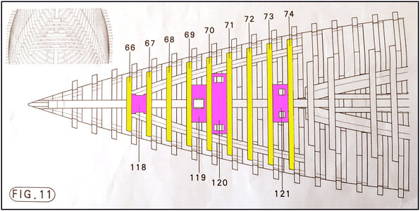
Of course I can just slide everything back 4.5 mm. The recesses are for the standing beams for the windlass and bowsprit.
I will still build the windlass scratch and the bowsprit can be adjusted. A matter of continuing to look ahead and keep planning.
Well, I still need some time to weigh up all the pros and cons.
Gr. Peter
In my post #372 I already explained that I am not going to let the top deck beams end between the frames, but rather shorten and 'lock' them between the 'Clamps', as shown in The Saga.
Nothing is shown for the beams in the lower floors. With the exception for partly the small beams between the 'Stringers', see my post #445.
To view what I mean: In the YQ manual, the beams are placed in front of the frames and extend between the frames:

I highlighted them in yellow. (Blue is coming soon
But this seems not logical to me, because how do they get the beams attached to the frames at the ends? There is almost no space for hammering between the frames.
But in this detailed account of the construction of the model by G. Bodnar using the drawings of P.F. Eisnor,
(see link: http://www.modelshipbuilder.com/page.php?26)
you can see he placed the beams on the frames:

Here I have placed 2 beams in the hull to show the difference:

The front should of course still have the correct chamfer.
Thanks to the photo I can still see some pencil lines. Occasional shot of the frames while accentuating before sanding
If I move the beams to on the frames, that means that everything shifts 4.5 mm / 0,177” backwards. So also all blocks, with recesses, between the beams.
I made it blue in the photo of the YQ manual (see above).
Not a problem, because at the front of both blocks I can remove 4.5 mm.
At the raised lower deck at the front I have to see what can and cannot be done there. Because there are more blocks placed between the beams:

Of course I can just slide everything back 4.5 mm. The recesses are for the standing beams for the windlass and bowsprit.
I will still build the windlass scratch and the bowsprit can be adjusted. A matter of continuing to look ahead and keep planning.
Well, I still need some time to weigh up all the pros and cons.
Gr. Peter
Last edited:
There is a lot of careful and precise filing and fitting in the model and you are doing very well. RichIn order to determine where I can or cannot reach with the 1st layer of paint or oil, I am further thinking about the deck beams.
In my post #372 I already explained that I am not going to let the top deck beams end between the frames, but rather shorten and 'lock' them between the 'Clamps', as shown in The Saga.
Nothing is shown for the beams in the lower floors. With the exception for partly the small beams between the 'Stringers', see my post #445.
To view what I mean: In the YQ manual, the beams are placed in front of the frames and extend between the frames:
View attachment 245512
I highlighted them in yellow. (Blue is coming soon)
But this seems not logical to me, because how do they get the beams attached to the frames at the ends? There is almost no space for that.
But in this detailed account of the construction of the model by G. Bodnar using the drawings of P.F. Eisnor,
(see link: http://www.modelshipbuilder.com/page.php?26)
you can see the beams are on the frames:
View attachment 245513
Here I have placed 2 beams in the hull to show the difference:
View attachment 245514
The front should of course still have the correct chamfer.
Thanks to the photo I can still see some pencil lines. Occasional shot of the frames while accentuating before sanding
If I move the beams to on the frames, that means that everything shifts 4.5 mm / 0,177” backwards. So also all blocks, with recesses, between the beams.
I made it blue in the photo of the YQ manual (see above).
Not a problem, because at the front of both blocks I can remove 4.5 mm.
At the raised lower deck at the front I have to see what can and cannot be done there. Because there are more blocks placed between the beams:
View attachment 245515
Of course I can just slide everything back 4.5 mm. The recesses are for the standing beams for the windlass and bowsprit.
I will still build the windlass scratch and the bowsprit can be adjusted. A matter of continuing to look ahead and keep planning.
Well, I still need some time to weigh up all the pros and cons.
Gr. Peter
Thanxs, Rich. The advantage is that I am not in a hurry .....There is a lot of careful and precise filing and fitting in the model and you are doing very well. Rich
Regards, Peter
Peter…she is looking good as always!In order to determine where I can or cannot reach with the 1st layer of paint or oil, I am further thinking about the deck beams.
In my post #372 I already explained that I am not going to let the top deck beams end between the frames, but rather shorten and 'lock' them between the 'Clamps', as shown in The Saga.
Nothing is shown for the beams in the lower floors. With the exception for partly the small beams between the 'Stringers', see my post #445.
To view what I mean: In the YQ manual, the beams are placed in front of the frames and extend between the frames:
View attachment 245512
I highlighted them in yellow. (Blue is coming soon)
But this seems not logical to me, because how do they get the beams attached to the frames at the ends? There is almost no space for hammering between the frames.
But in this detailed account of the construction of the model by G. Bodnar using the drawings of P.F. Eisnor,
(see link: http://www.modelshipbuilder.com/page.php?26)
you can see he placed the beams on the frames:
View attachment 245513
Here I have placed 2 beams in the hull to show the difference:
View attachment 245514
The front should of course still have the correct chamfer.
Thanks to the photo I can still see some pencil lines. Occasional shot of the frames while accentuating before sanding
If I move the beams to on the frames, that means that everything shifts 4.5 mm / 0,177” backwards. So also all blocks, with recesses, between the beams.
I made it blue in the photo of the YQ manual (see above).
Not a problem, because at the front of both blocks I can remove 4.5 mm.
At the raised lower deck at the front I have to see what can and cannot be done there. Because there are more blocks placed between the beams:
View attachment 245515
Of course I can just slide everything back 4.5 mm. The recesses are for the standing beams for the windlass and bowsprit.
I will still build the windlass scratch and the bowsprit can be adjusted. A matter of continuing to look ahead and keep planning.
Well, I still need some time to weigh up all the pros and cons.
Gr. Peter
As far as shifting everything, in order to put the cross beams on top of the frames, see below…
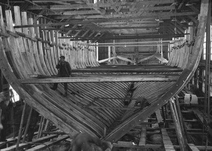
you can clearly see the crossbeam is not on top of the frame in this picture, it is between the frames. Is this a support beam for construction purposes only? I don’t know. All I can say for certain, is that it proves it is feasible to do it that way.
However you have freedom to decide what path you want to take, using your own logic, on your model.
Last edited:


