Thanxs Rich.Peter, You are progressing very well and with precise care that will return large dividends. Rich
I only think the top nails in the mast rests are a little to big.
Regards, Peter
 |
As a way to introduce our brass coins to the community, we will raffle off a free coin during the month of August. Follow link ABOVE for instructions for entering. |
 |
 |
The beloved Ships in Scale Magazine is back and charting a new course for 2026! Discover new skills, new techniques, and new inspirations in every issue. NOTE THAT OUR FIRST ISSUE WILL BE JAN/FEB 2026 |
 |
Thanxs Rich.Peter, You are progressing very well and with precise care that will return large dividends. Rich

Thanxs Henk.I understand the choice of nails, but given the weight that the mast foot has to bear, an understandable choice on your part to put in some other nails.
Nice challenge to planks the inside, and nice to build "Out of the box",
Respect

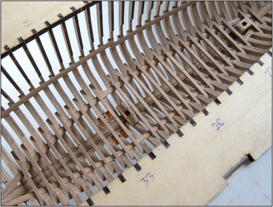
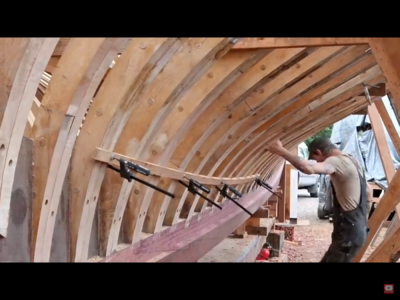
Looking great Peter! Fantastic job as usual!The next step in the hull is the inner wall planking on the port side, starting on the lowest part between the keelson and the bearing beams of the lower floors. That is no part of the kit, but it is my choise.
But I still have not received the ordered wood.
So, started with the preparation of the lower floor beams and mast steps. The YQ-way, as wrote above in post #496.
Sanded all the char from the 27 beams and aligned them on the bearing beams. I had to flatten a little bit of the starboard side bearing beam:
View attachment 246092
It needs a little more on the starboard side, thanks to the picture.
I have marked all the beam in the middle, so I could align them on the keelsom to check the fitting.
When the lower planking is done, the beams where attached to the bearing beams, inclusive the bolts. And sanding off the marks.
Then I installed the 4 copper water wells, I introduced them to you in my posts #233 and #242:
View attachment 246093
Around them and between the lowest point between the frames comes the cast iron parts for the ballast. But that will be dumped later.
I could use my cross-table and mill for the first time, to mill the bottom of the main mast step. To fit over the keelson and sisters keelson:
View attachment 246094
And the fitting:
View attachment 246095
From the side, the parts are reinforced with the same bolts as in the keelson and bearing beams. From the top, the step is secured to the frame and to the sisters keelson with stronger bolts.
And the mast step for the fore mast:
View attachment 246096
The mast step is also secured to the floor beam that lies in front.
Now you can see what different types of light affect the color of the wood.
And a overview:
View attachment 246097
Until the wood is in, I'll continue with the pre-work on the other lower floor beams.
Regards, Peter
Heinrich, Thanks for your reply with some ‘supertatives’. I appreciate your overview on all BN-builds.Hoi Peter. There are many commendable aspects to comment on here. .......
Thank you, mate!Looking great Peter! Fantastic job as usual!
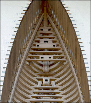
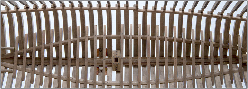
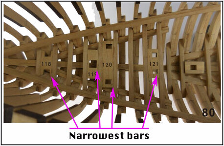
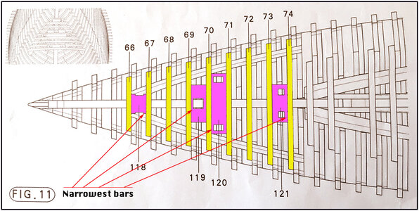
I came to the same conclusion, which way the narrow side faces ensures proper alignment! Good job recognizing that!A small addition for the other builders for placing the blocks between the front beams. I was puzzling in which position you should place them.
There is a difference between the manual foto 80 on page 14 and the drawing fig.11:
View attachment 246444
View attachment 246445
In the drawing, the middle 2 blocks has the narrowest bar to the front. My choice was to follow the picture.
You only have to make the choice yourself whether you want to have the laser lines in sight or not. Now it shows if the blocks are composed of multiple pieces.
Regards, Peter
Thanxs, Dean.I came to the same conclusion, which way the narrow side faces ensures proper alignment! Good job recognizing that!
No they lined up perfectly! The deck planks will have to be aligned to ensure they are correct, if not using the supplied sheets. I used the correct posts and put them in place when putting down the deck planks. However, the placement of the deck beams is the true alignment needed, as the edge of the notches in the beams need to align with the openings below. Once again, put the posts in place and ensure they are aligned when installing the deck beams. Then the planks will work around that. Hope that makes sense!Thanxs, Dean.
And your uprights slides right into position? Or did you have to adjust them?
Regards, Peter
Top, that will be the order of placement and alignment, not using the sheets!No they lined up perfectly! The deck planks will have to be aligned to ensure they are correct, if not using the supplied sheets. I used the correct posts and put them in place when putting down the deck planks. In fact, that way ensures a good alignment,as opposed to using the sheets, which may or may not align properly.
I edited my post to say the deck beams have to be aligned when installed so the notches align with the posts, which I temporarily placed to ensure this!Top, that will be the order of placement and alignment, not using the sheets!
Regards, Peter

Hi Henk,Well noticed by both of you
I wouldn't have seen..
Those uprights, where are they mentioned in the manual?
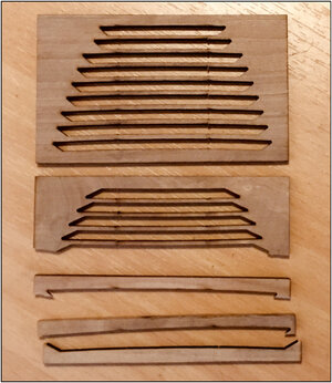
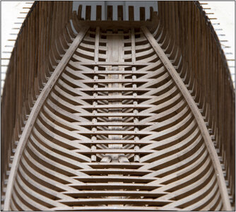
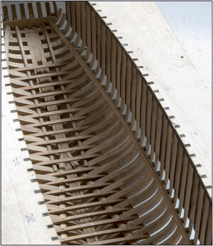
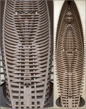
Looking good Peter!From the sheets from which the middle lower deckbeams came, I was able to make the floor beams for the rear floor on the stringers. Because those rest partitions were nice in thickness and had the right camber:
View attachment 246570
Fitted on the stingers and between the frames, cut them in the right size, remove the char, marked the holes and drilled them:
View attachment 246571
Drilled also the holes in all the other beams:
View attachment 246572
An overview from the back, together with a total overview.
Both photos merged, otherwise it will be such a long narrow photo.
View attachment 246573
Regards, Peter
Thanxs Dean, for thinking along. I visualized the structures on the deck and adapted my plan to them. The stairs run from back to front and then lead to the cabin. There are also level differences visible in the drawings in The Saga, so with AL-FI in it, I think my plan will fit.Looking good Peter!
One thing about the stern area, the main cabin is there, with stairs that go below from the doors at the upper deck by the wheel house. So I would assume that floor or deck of the cabin area would be perpendicular to the stern deck.
How that was framed internally I am not sure. But I don’t think the cabin floor was at an angle. Just something to consider if you add the cabin area.
