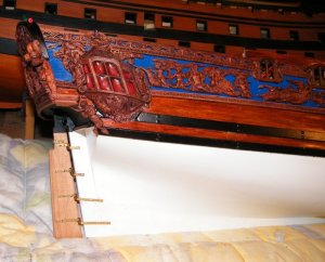
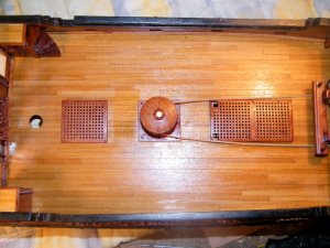
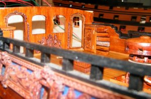
ZHL Royal Caroline Kit, scale 1/30

G'day John
I've just checked my kit and the rudder are in two halves. I think I'll will trim the excess away from the inner two facing edges before glueing them together.
Havagooday mate
Greg
 
Last edited:
G'day Greg, mine came in two parts as well, but it wasn't till after I had glued them, I found out they needed to be thinner, how are you going to trim the inner faces, a drum sander would be ideal if you have access to one,

best regards John.
 
G'day John
I've a belt sander with variable speeds. I can place a little more pressure on the corner that has to be thinner, of course I will checking the among that I will be removing every few seconds with my micrometer. Just to be sure!
:oops:
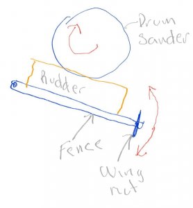
I have a bench top drill press, that I have been planning to make a drum sander box for it. When using a drum sander, the amount that you would take off would be uniform.
Do you have any ideas that I could do to the drum sander to make it as a variable 'bite' sander?

20180315_073028.jpg

Please excuse my rough sketch, but this is the only way I can think of to do make a drum sander. The variable thickness guide will hold the non sanding edge flat as it passes the drum sander. I can't think of any else to add to only take off 'one corner' only.
;)
There is one thing that I'm amazed that wasn't put on the rudder was the separate 'timbers joins' that made up the rudder. I reckon I might scrap some lines myself.
That's my plan anyway.
:rolleyes:
Havagooday
Greg
 
While working on the rudder I decided to do most of the accessories that go with it, the leather boots and tiller arm etc,
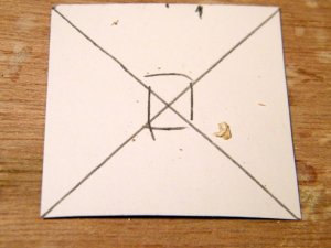


670.jpg
I cut some light cardboard to the shape of the material for the leather boots, to make a template with,
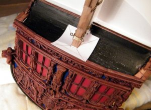


671.jpg
then i placed it on the upper part of the rudder so i could mark the shape it needed to be,
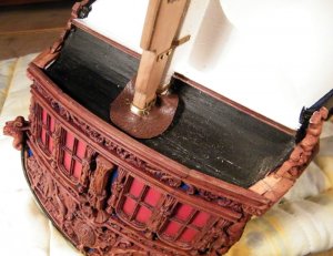

672.jpg
then I copied that shape onto the material provided and cut it out,
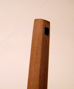

673.jpg
next up was the Tennon joint for attaching in place the tiller arm, shows the hole cut through
the top of the rudder,
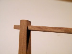


674.jpg
the tiller arm in place after the rear was reduced in thickness to fit through the rudder head,
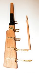

675.jpg
the rudder with the tiller arm next to it,


676.jpg
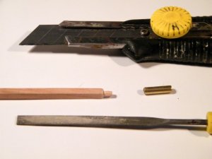
the front of the arm it had to be reduced to a round section so as to be able to take the brass tube as a
reinforcement, I used the knife to score around the arm and also to whittle it back and then finished it
off with a small flat file,
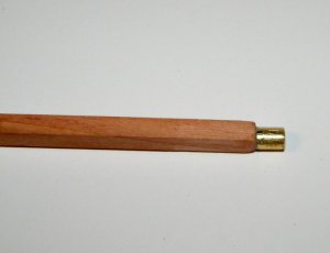


677.jpg
the brass reinforcement glued in place,


678.jpg
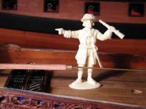
next up was to work out the height that the front part of the tiller needed to be raised to, I have some
1/30 scale figures so I used one of those for reference, I thought it would have to come up to around
his waist height to be comfortable and practical to use,


679.jpg
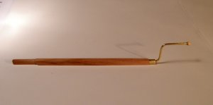
the finished arm, all apart from the varnish and paintwork,


680.jpg
and temporarily in position


681.jpg
and lastly a pic of the rudder it will be painted white below the black,
 
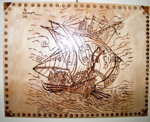
My Admiral does wood burning as one of her hobbies and to-day she surprised me and gave me a special wood burning she had done of a Xebec, I thought that it was very good and would like to share it with you all,

best regards John.


682.jpg
 
Last edited:
My Admiral does wood burning as one of her hobbies and to-day she surprised me and gave a special wood burning she had done of a Xebec, I thought that it was very good and would like to share it with you all,

best regards John.

This is realy looking good !
and this time I mean not only your rudder......
 
G'day John and Maureen
Ohwhattabeauty!
That burnt wood painting is absolutely spectacular. Could you please pass that message to Maureen please mate.
The tiller is also of the highest quality, same as your normal standards.

I've been looking at other RC on the net and this model below has a point that I wasn't thinking about and I can't find any other examples on the internet with this 'EXTRA' rigging.
20180316_074538.jpg
The photo below shows that pullies were used to stear the yacht instead of a sailor moving the tiller from side to side.
I realized the use of pullies must be used because the strenght needed to move the tillie, would have to be of superhuman strengh.
20180316_074628.jpg
I would also think that the pullies would have been connected to the spanker sail. With these two combinations it would have been easier to navigate a tight course.
Havagooday mate
Greg
 
Thanks guys, I passed all your likes and comments on to the Admiral and she said to say a big thank you,

best regards John.
 
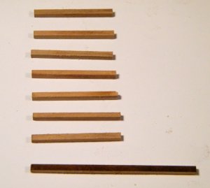
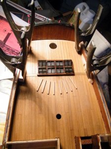
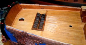
Just in front of the skylight and below the end of the tiller there are eight wooden bars attached to the deck,
there purpose is to enable the Crew man steering the boat to be able to have something he can use for leverage
when moving the tiller from side to side, so he can push his feet up against the bars,


684.jpg
These are the bars after being cut to size, and the bottom bar has yet to be cut and sanded,


683.jpg
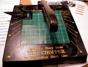
And this is the chopper that I used to cut them all to the same length,


685.jpg
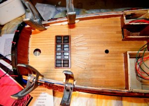
and the bars in place, I have also glued down the after most part of the quarter deck as well,


686.jpg
another view
 
Just like to say I did not use the wood profiles shown in this post, I followed Uwe's advice and made some
see post 516 a couple down the page


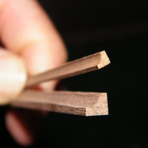
They include some strip wood in the kit for the water ways it is square in section and has to be shaped,
I already have some strip wood that is already shaped and I was thinking about using it, iv'e attached a
couple of pics below, it will be the smaller section that I will use,


687.jpg
This is the smaller section


689.jpg
and again

691.jpg


Thanks for looking in,

best regards John.
 
Last edited:
G'day John
I got a dremel router table and about 10 different router bits. This router bench would be a perfect solution for me, so I can do those channels strips. I think I'll use my anti cut working gloves as I'll be doing it. Just to be on the safe side.
Havagooday mate Greg
 
As a waterway should the curve of the shaped area of the cross section not start flash or at the same height like the deck-planking? More or less the same to the vertical bulwark......because usually this plank is included in the structure.
If yes you have to sand it down on two sides......or sanding the original strip wood from the kit to a triangle.... only a thought....
 
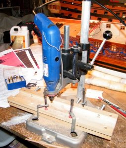
So I took Uwe's advice and set up my small Dremel type drill stand and got to work,


695.jpg
My set up with a home made sliding table, for cutting the 45o angle on these I left the
sliding table off and just slid the wood along between the back of the table and the router bit,


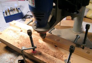
692.jpg
Close up, please note that for this pic I cut the angle first and then switched the drill off while I took the pic,


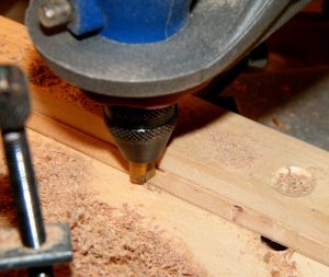
693.jpg
another close up,


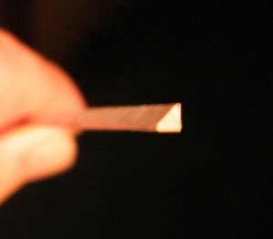
694.jpg
and the finished water way, sorry its a bit fuzzy.
 
Last edited:
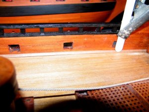
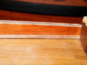
After making the water ways the next thing is to fix them in place,


699.jpg
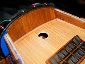
The waterways on the quarter deck with the frames for the sheaves also attached, the deck and waterways have
yet to be varnished,


700.jpg
close up view,


696.jpg
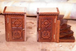
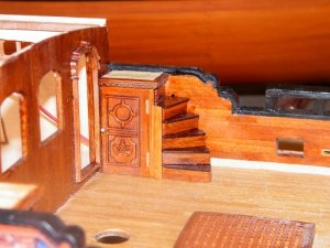
the companion ways ready for attaching, I had to add a strip of wood down the cabin wall side so as to keep
the door knobs clear of the wall,, I will varnish the strip before attaching,


697.jpg
and fixed in place, you can see the waterway also fixed in place,


701.jpg
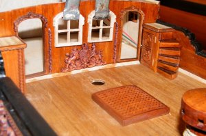
The middle windows held in place with clamps so i can see where to attach the carvings,


698.jpg
the port side waterway in place,


702.jpg
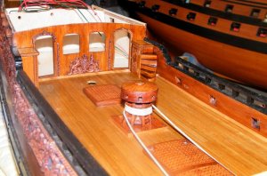
and after the deck and waterways have had a coat of matt varnish,


703.jpg
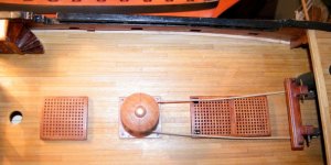
overhead view of the waist after a coat of matt varnish,


704.jpg
nd a view over the waist rails,
 
Last edited:
G'day John
I can see what you mean about the companion ways. 'Tight as a fishes bum' as a very polite Ozzie's expression goes.
;):p
Again thank you for giving us your step by step pictorial instructions.
Look it great mate!
Havagooday
Greg
 
Back
Top