HMS Alert 1777 by Danielw

Jimsky, My experiment with the ebony putty was a dismal failure... The putty/filler left a smear around the holes. I have a reference somewhere in my chaotic library that refers to fastenings of this period... gonna go in and find it. The search continues
 
Re fastenings...The Anatomy of Nelson's Ships (Longridge) states (and I paraphrase)"Copper bolts were the standard means of fastening the important timbers together.....Holes were bored slightly smaller than the bolt then the copper bolt was then driven in and clenched over a plate....nuts as we know them now were not used with the bolts on a ship as described here..."
 
Re fastenings...The Anatomy of Nelson's Ships (Longridge) states (and I paraphrase)"Copper bolts were the standard means of fastening the important timbers together.....Holes were bored slightly smaller than the bolt then the copper bolt was then driven in and clenched over a plate....nuts as we know them now were not used with the bolts on a ship as described here..."
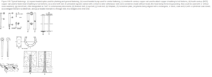
Something like this:
Obviously they didn't have the power tools in the day.
 
As a result of Jolley Roger's great template idea, I made up one that will slip over the rib thus ensuring it stays where it is supposed to..Photo of prototype is attached.
I am still unsure whether to use metal or plastic or whatever to simulate the fastenings..

20200928_152625[2].jpg
 
A bit of an update..pictures attached.I want to get those ribs bolted and faired just to see how accurate I am.
The drilling of the simulated fastenings is causing a bit of concern. One wrong drill hole and it sticks out like the dickens.
I really do need to bite the bullet.
Cheers, Danw

20200930_081408[1].jpg20200930_081330[1].jpg
 
Hi Jim, Not sure yet .I am still "tooling around" with it at the moment. Off to work at the moment. I'll keep you posted. Cheers
 
Here is from Peter Goodwin, a section called 'Frame construction 1750 -1811

...Now that there were first, second, third, and fourth futtocks and two toptimbers, selection of timber were made somewhat easier, and wastage was minimized. butt joints were replaced either by scarph or by 'anchor pieces' or cross chocks, fastened by trennals, although the joint between the third and fourth futtocks and their respective toptimbers was a plain flat scarph.

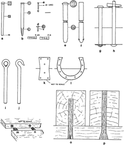
Another interesting image from illustrated Glossary of Ship and Boat Terms J. Richard Steffy
specifically 'o' and 'p'
1601424413701.png
 
A bit of an update..pictures attached.I want to get those ribs bolted and faired just to see how accurate I am.
The drilling of the simulated fastenings is causing a bit of concern. One wrong drill hole and it sticks out like the dickens.
I really do need to bite the bullet.
Cheers, Danw
...I think, for consisting drilling, you would need a jig\template but...I like your template for marking the holes starters. But drilling, using this jig will be impractical, IMHO. The holes will be enlarged after a few drilling frames. All the frames are different in shape\size it would be difficult making jigs to suit each frame. I think a drill press with a coordinate table\vise or mill will be a good idea.
 
Hallo my friends, a little bit late in this discussion, but I want to confirm, that (according my knowledge) the chocks are fixed with the futtocks, floor timbers, top timbers etc. with iron bolts which went through the complete wood.
Wooden dowels would be never so strong to keep the complete system "Frame" stiff enough.
Here is the drawing from Jim in bigger scale:
oxfordhb-9780199336005-graphic211-full.gif
Type "g" f.e.
 
Greetings, An update...
All ribs have been fitted, there will now be much grinding , polishing and gnashing of teeth and wailing..
As can be seen there is a fair amount of work to do.
In spite of the fact that I chose not to "chamfer" certain ribs as per the instructions it is not an onerous task to fair the internals.
It is certainly a good feeling having reached this stage albeit a very early stage as I can now get a better mental picture of the processes of the build.
I can clearly see several places that were attempted early in the build that will need to be revisited..But hey; all good fun!
Once again, sorry about the quality of the pictures.
Whilst waiting for glue to dry I got to thinking......
These days macro photography is available to all. With modern technology one can see every minute detail of the model: now I wonder if that model, viewed with the naked eye from a distance ,say in keeping with a museum viewpoint, would it look as good and would it have a certain emotional presence rather than being a clinical cold object?
There are those among you who I believe, would say I should use a fast setting glue to avoid these thoughts.!
20201002_201844[1].jpg20201002_201840[1].jpg20201002_150244[1].jpg
 
Paul, I have to agree about the ratlines.....At the outset I mentioned that this project should be viewed as a single malt whiskey.. taken slowly and savoured...
Well after those ribs.. Just get me a strong drink for heaven's sake!!!!!
 
Looking great danielw!
Can you remember "how" you attached your pictures? I can't enlarge the third one - well, it is large enough, just tried because of the software-updates, the first two behave "normal" ;)

I can so much follow your point about "macro photography"!
Though I mainly work with my magnifier lamp and am happy with the result: when I look at a picture I always find a ridge or spot I wasn't even aware of :oops:
 
Back
Top