LT100 My Way
With this build log there is a lot of ground to catch up on I have been building this model for more than 20 years. I do not profess to be an expert builder, nor that this is an exceptional model, especially considering that this is only my second scratch built model, however my intention is to build the best model I can (this is true most of the time). My first reasonable scratch build being a simple hard chine cabin cruiser. Most of the models I have built have been plastic kits.
My intention with this project was to build a working model without many compromises, that is to say when out of the water you would not be able to tell it is a working model.
I welcome constructive comment.
I hope people enjoy the journey with me.
Looking around for a scratch build project, something that wouldn’t take too long (ha-ha) or be too complex or too large, I found that I really liked the look of steam drifter trawlers, a wooden prototype being preferred as I could build a model hull out of wood then build a steam plant to power it; therefore the model would have some similarity to the original even if internally it wasn’t a replica. So the decision was made to build myself one, I started searching for suitable plans, this was in a time before the internet when things weren’t just a click away, therefore I relied on the couple of plans catalogues that I had in my possession.
Plans were found in the MAP Plans catalogue, then this project got off to something of a false start in 1990 with the purchase of a set of plans drawn by R. A. Neville to a scale of 1/24, from the Plan Shop in New South Wales Australia these are for a typical Wooden Steam Drifter, I am not sure when these plans were first printed, however I have inherited a copy of Model Engineer published in September 1959 which is the first of 4 articles titled, How to build a Wooden Steam Drifter, written by R. A. Neville (I didn’t find this article until many years after starting work on this project!) I wasn’t quite happy with these plans, being more interested in building something that represented an actual vessel, so I sat on them for quite a while umming and arr-ing, thinking they are not quite what I wanted.
Then to my amazement and elation, on the cover of Model Boats in April 1993 was a beautifully made model, that had been entered into Class C9 kit class at the 1993 Model Engineer Exhibition, of LT100 built by Robin Butler, winning a Silver medal, and guess what next month there were to be plans for this trawler, wow just what I wanted!
Life got in the way of hobby as it usually does and it wasn’t until a few years later in 1996 that I purchased the plans drawn of Formidable LT 100 by James Pottinger to a scale of 1/33, along with the book From Tree to Sea by Ted Frost, this is a wonderful book about the construction of LT 100 drawing from Ted Frosts memories as an apprentice ship wright.
The plans arrived, then I had them enlarged to what I thought was 1:24 scale, as mentioned earlier I intended to power the model by steam, I went off and measured the opening for the wheel house and I found I could comfortably fit the 3 ½in diameter boiler I was thinking of building through the opening. Having no experience with steam at all, I imagined that steam plants would require quite a bit of servicing, with this in mind I thought it was important to be able to remove the entire steam plant easily for routine maintenance. Next step was to get some plans for an engine.
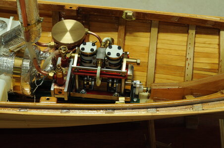
Probably in 1996, my dad and I went to Kilsyth (an outer suburb of Melbourne, Australia), where Live Steam Supplies of Victoria were, they specialised in miniature steam in all its aspects. Whilst there I purchased plans for a ½ in bore ½ in stroke, twin cylinder double acting oscillating steam engine designed by Basil Harley, published by Model Maker plans service. Probably first printed in July 1983, I have the August 1983 Model Boats with part two in a series of articles to build the engine and boiler along with a 42in long steam launch, once again I didn’t find this article until much later after purchasing the plans even though this was a magazine I had bought!
I had already decided to make the centre flue boiler designed by Peter Arnot. Peter ran an excellent series of articles in Model Boats for a Vee 4 steam engine, boiler and associated equipment throughout the year of 1993, I intended to purchase some 3 ½in copper pipe as illustrated in the plan. Unfortunately Live Steam Supplies of Victoria didn’t have any 3 ½in copper pipe, turns out this isn’t a size commonly used in Australia, what to do, luckily I had bought along the trawler plans and after a few quick measurements were taken, a rash on the spot decision was made, (this would latter cause problems) I purchased two pieces of 4in diameter copper pipe that were cut to length, along with flat sheet copper for the end plates, smaller diameter tubing, a few packs of solder on nuts and tails along with other various items including a Cheddar ceramic gas burner.
The steam engine and boiler were started along with the work boat, work proceeding roughly in parallel.
Most people start with the hull, however I decided to start making the work boat first, my thinking being if I can make a small clinker built boat to the standard I wanted then the rest should be achievable, also I wouldn’t be in such a rush to finish what is really “just a fitting” for the project, therefore possibly doing a better job.
After reading the clinker-built boat section of “PLANK-ON-FRAME MODELS and SCALE MASTING & RIGGING Volume 2” by Harold A Underhill a start could be made.
I wanted to use Huon pine, for most of this little boat, this is a very slow growing timber unique to Tasmania in Australia, which was used to build real ships and boats from, due to its ability to not rot even when submerged, it also has a straight, fine grain and generally pale in colour.
I made a start by spending a day at dad’s using his table saw to cut up some blocks of Huon pine into strips to make up a “kit” of material. This material I had bought back from Tasmania on my honeymoon, packed into our suitcases to my wife’s bewilderment. Then making a building board and former's from MDF (not the best material to use as the dust is very bad for you, I was unaware of this at the time). The keel was fabricated from several pieces of an unknown hard wood all pinned together with homemade bamboo pins, a Huon pine transom being pinned to the stern post also keel doublers attached for planks to rest on. I would like to say that I could not have made the work boat without Harold Underhill’s book, there was a lot of reading then rereading combined with head scratching going on during the build. The main difficulty was to generate the shape of planks. At one point I nearly scrapped the whole thing as I couldn’t seem to get the planking just right, however after some consideration I pressed on with the attitude it doesn’t really matter if this one is not perfect I will learn lesions in building it and I can always build another if it isn’t up to scratch. Once templates were made the plank would be cut and steamed then clamped into position, left there for a few days then glued on with Cyanoacrylate and pinned to the previous plank, making sure not to pin it to the building frame.
After planking the hull was removed from its jig then ribs, benches, floor boards, rubbing strake and knees were added, some artistic licence was taken, I didn’t follow the plans completely choosing to not add grab lines like you would see on a life boat and a device that I was unable to determine its purpose mounted on the transom. Next oars were made, these are not shown on the plans, I didn’t want to make paddle’s, so I looked through books that I have trying to determine proportions and came up with something that looks like an oar to me, I made these from Huon pine in two parts. Next came the crutches and sockets, Brass tube was used for the sockets being fitted into holes drilled. Next the crutches, these were fabricated from brass wire and fine chain silver soldered together, when I am silver soldering small parts I use a technique my dad taught me, that is to cut off the required amount of solder and once you have heated the flux a little to boil most of the moisture away, then place the solder using tweezers where it is required, the solder will stay in place because most of the moisture has gone from the flux, gently apply heat and you should have a very neat job. While on the subject of soldering a low-cost alternative to fire bricks is to use what is called Hebel in Australia this is a lightweight product used in buildings and landscaping it is an aerated concrete sold in blocks. Once the flux was cleaned up, they were painted black using Humbrol enamel. Using a Teak coloured wood stain, I masked then stained the top strake down to the rubbing strake. The inside and top strake now received a couple of coats of satin varnish. The rest of it received a few coats of Humbrol satin white airbrushed on. In the end after it was finished, I hadn’t quite achieved what I set out to do however, I was quite happy with my little work boat even with its short comings.
View attachment 182851View attachment 182852View attachment 182853View attachment 182854View attachment 182855View attachment 182856


.JPG")

")
.JPG")

.JPG")
.JPG")
.JPG")


.JPG")

.JPG")

.JPG")

.JPG")
.JPG")
.JPG")
.JPG")
.JPG")

