YQ Bluenose by Johan [COMPLETED BUILD]

No building this past week, nor the coming weeks, but time to think things through a little bit more ánd, more important, reading through some blogs of my predecessors.
Interesting reads, to say the least.
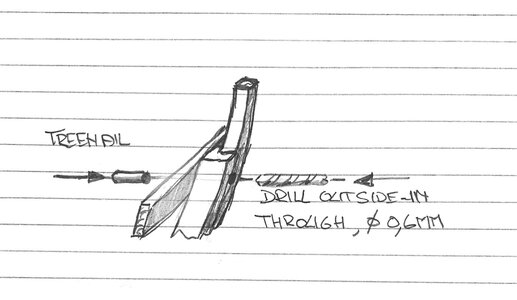
One thing which concerns me is the attachment of the beam supports, they are supposedly attached, from the inside out, to the frames. Especially towards the front, there's precious little space to do anything.
So my current thinking is to drill from the outside in and than add treenails from the inside. Fill up the holes with an appropriate filler.
A75E0DD3-CC60-485F-9ECD-BC5A7065E0BE.jpeg

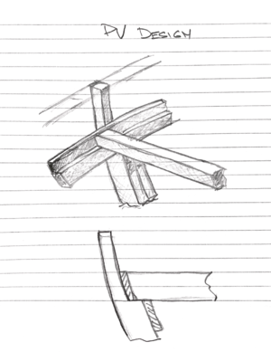
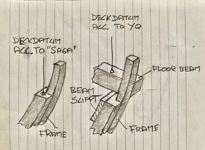
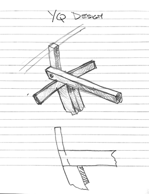
Then attaching the upper deck beams. I read through Peter's blog, did some sketching and I am afraid I'll have to follow Peter's lead in this; it's best matching the Bluenose design per the Saga. The actual configuration is a lot more complex, but I'll leave that to the real expert builders.

YQ'S solution:
0FD3B943-7762-434A-AA33-8488C73EA8A0.png

Peter Voogt's solution:
41A42BA7-9C92-4AF1-BDB4-7726FE46E8F3.png

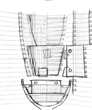
Furthermore, I want to add partial floors in the forecastle, the fishhold and the captain's cabin. Also to be added are the partitions between the various compartments. Since there is little detail for the captain's cabin, I started some initial sketching, to visualize my thoughts. This still requires some maturation, but gives an idea which direction I want to go.
C4C8B3FE-C750-4C62-BE17-A10863DD3AE5.png

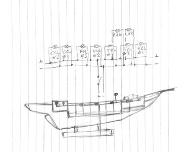
And finally, and I agree, it's still a long way out, but I want to add some lights to the model. Since it will impact the ship's structure, at least to some extent, I want to know upfront what I have to deal with; routing, feedthroughs, power supply, switches...
2C0B6240-5E88-4F28-952C-14A8CA785BC0.jpeg
 
Last edited:
One thing which concerns me is the attachment of the beam supports, they are supposedly attached, from the inside out, to the frames. Especially towards the front, there's precious little space to do anything.
So my current thinking is to drill from the outside in and than add treenails from the inside. Fill up the holes with an appropriate filler.
Hi Johan,
Because of the shape of the hull, I could dril all the holes from the inside. Those on the front with the hand drill.
Then attaching the upper deck beams. I read through Peter's blog, did some sketching and I am afraid I'll have to follow Peter's lead in this; it's best matching the Bluenose design per the Saga. The actual configuration is a lot more complex, but I'll leave that to the real expert builders.
As you have drawn in your sketch 'PV-design', on the bearing beams comes against the frames the so-called 'clamps'. Then you have to shorten all the deck beams by the same amount on the starboard side as on the port side. Especially important with the composite with the short between beams.
Furthermore, I want to add partial floors in the forecastle, the fishhold and the captain's cabin. Also to be added are the partitions between the various compartments. Since there is little detail for the captain's cabin, I started some initial sketching, to visualize my thoughts. This still requires some maturation, but gives an idea which direction I want to go.
Very good to make this drawings. That gives direction to what will give a good interpretation of your plans.
Regards, Peter
 
Because of the shape of the hull, I could dril all the holes from the inside. Those on the front with the hand drill.
In that case, I might need to have a closer look, especially at the upper deck support beams. To me they appeared to be highly inaccessible.
Then you have to shorten all the deck beams by the same amount on the starboard side as on the port side.
Yep, I got that from taking a close look at your pictures from your blog. Thanks for pointing it out though.
Very good to make this drawings. That gives direction to what will give a good interpretation of your plans.
Sketching helps me getting these kind of details out of my head. Otherwise I keep on turning these issues over again and again. Now that it's visualized, I can put it to rest.
More detailing still required though.
 
No building this past week, nor the coming weeks, but time to think things through a little bit more ánd, more important, reading through some blogs of my predecessors.
Interesting reads, to say the least.
One thing which concerns me is the attachment of the beam supports, they are supposedly attached, from the inside out, to the frames. Especially towards the front, there's precious little space to do anything.
So my current thinking is to drill from the outside in and than add treenails from the inside. Fill up the holes with an appropriate filler.

View attachment 288524

Then attaching the upper deck beams. I read through Peter's blog, did some sketching and I am afraid I'll have to follow Peter's lead in this; it's best matching the Bluenose design per the Saga. The actual configuration is a lot more complex, but I'll leave that to the real expert builders.

YQ'S solution:
View attachment 288525

Peter Voogt's solution:
View attachment 288526

Furthermore, I want to add partial floors in the forecastle, the fishhold and the captain's cabin. Also to be added are the partitions between the various compartments. Since there is little detail for the captain's cabin, I started some initial sketching, to visualize my thoughts. This still requires some maturation, but gives an idea which direction I want to go.

View attachment 288528

And finally, and I agree, it's still a long way out, but I want to add some lights to the model. Since it will impact the ship's structure, at least to some extent, I want to know upfront what I have to deal with; routing, feedthroughs, power supply, switches...

View attachment 288529
First off, I congratulate you on your very well drawn "sketches" with precise steady linework.. . none the scratchy style.
Your progress and questions are well placed and I am sure will produce the leads that you ask for incorporation.
Rich (PT-2)
 
First off, I congratulate you on your very well drawn "sketches" with precise steady linework.. . none the scratchy style.
Your progress and questions are well placed and I am sure will produce the leads that you ask for incorporation.
Rich (PT-2)
Thank you Rich! I appreciate your congratulations.
 
Great thinking and designing Johan. That is where I am useless specifically if it is only on paper - I can only start visualizing if I something in hand.
 
Great thinking and designing Johan. That is where I am useless specifically if it is only on paper - I can only start visualizing if I something in hand.
I'm pretty useless the other way around. First something needs to exist in my head, which then needs to be transferred to paper ir digital format. Finally, if that is still adding up, it becomes reality. I do have a tendency to overthink though...
 
I'm pretty useless the other way around. First something needs to exist in my head, which then needs to be transferred to paper ir digital format. Finally, if that is still adding up, it becomes reality. I do have a tendency to overthink though...
In my opinion overthinking is better and less likely to result in errors than "under-thinking" I have been accused or recognized as "overprocessing" matters where the other parties were not looking for details but a generality. Rich (PT-2)
 
Well, since I don't have acces to the actual Bluenose hardware at the moment, I have ample time to turn things over in my head. One of those things is the configuration of the hull/deck interface.
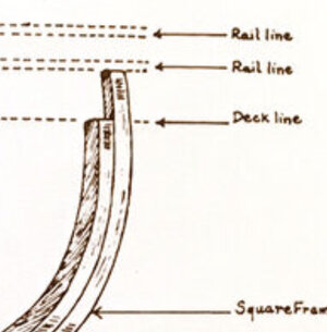
The Bluenose "Saga" shows the datum of the decks being the platform/notch as formed by the geometry of the double frames.

FCD2C75B-0CA8-4B1D-968C-AAFE1EA10D96.jpeg

The YQ frame design is consistent with the original design, however...

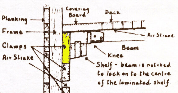
The top surface of the Bluenose (floor)beams are level with the deck line surfaces of the frames, see the cross section below.

DA5C73A0-E6B8-46C5-B6C9-34DB0A17C712.jpeg

Now, when looking at the YQ design, they appear to have taken a slightly different approach.

The top of the shelf, or beam support is level with the platform/notch, formed by the double frames. On top of that support rest the floorbeams and the top of the floorbeams then form the deck datum, or deck line. This means the deck datums have an offset, relative to the frame surface/notch, equal to the thickness of the beams.
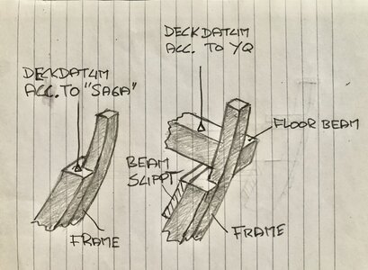
See also the sketch below, which is my interpretation of both designs.

30A4D1C2-ED50-43EE-B55E-FF84A23C2B66.jpeg

My question to those further ahead in the build, are my assumptions correct or am I missing something, or this just a case of YQ AL-FI?
 
Well, since I don't have acces to the actual Bluenose hardware at the moment, I have ample time to turn things over in my head. One of those things is the configuration of the hull/deck interface.
The Bluenose "Saga" shows the datum of the decks being the platform/notch as formed by the geometry of the double frames.

View attachment 289643

The YQ frame design is consistent with the original design, however...

The top surface of the Bluenose (floor)beams are level with the deck line surfaces of the frames, see the cross section below.

View attachment 289644

Now, when looking at the YQ design, they appear to have taken a slightly different approach.

The top of the shelf, or beam support is level with the platform/notch, formed by the double frames. On top of that support rest the floorbeams and the top of the floorbeams then form the deck datum, or deck line. This means the deck datums have an offset, relative to the frame surface/notch, equal to the thickness of the beams.
See also the sketch below, which is my interpretation of both designs.

View attachment 289645

My question to those further ahead in the build, are my assumptions correct or am I missing something, or this just a case of YQ AL-FI?
Related to the framing question I would note that what is called a "covering board" I would call it a "waterway" which is tapered upwards slightly and the top surface needs to be flush with the bottom of the scuppers for drainage off of the deck. Just a consideration. Rich (PT-2)
 
Related to the framing question I would note that what is called a "covering board" I would call it a "waterway" which is tapered upwards slightly and the top surface needs to be flush with the bottom of the scuppers for drainage off of the deck. Just a consideration. Rich (PT-2)
1644391326211.png

Johan, from your drawing, of the "Saga" design, it is not clear to me where the beam rests. The consideration of Rich is correct as the deck reference line must be the scuppers, at deck level, to facilitate the escape of excess water. By doing dry tests of the two projects and also positioning the bulwarks, you have the answer to your questions. The deck surface must be in line with the scuppers (or slightly higher).
 
Last edited:
View attachment 289713

Johan, from your drawing, of the "Saga" design, it is not clear to me where the beam rests. The consideration of Rich is correct as the deck reference line must be the scuppers, at deck level, to facilitate the escape of excess water. By doing dry tests of the two projects and also positioning the bulwarks, you have the answer to your questions. The deck surface must be in line with the scuppers (or slightly higher).

Related to the framing question I would note that what is called a "covering board" I would call it a "waterway" which is tapered upwards slightly and the top surface needs to be flush with the bottom of the scuppers for drainage off of the deck. Just a consideration. Rich (PT-2)
Morning Piero, Rich,

Yes, one can find different nomenclatures for parts with the same function, unfortunately, it's something we'll have to live with and sometimes requires us to exercise some patience... In my case, I hope you have patience in spades. ;)
The top surface of the waterways/covering boards need to be flush with the scuppers, no argument there. It's something Peter Voogt (@Peter Voog) already mentioned ánd addressed in his superb build.
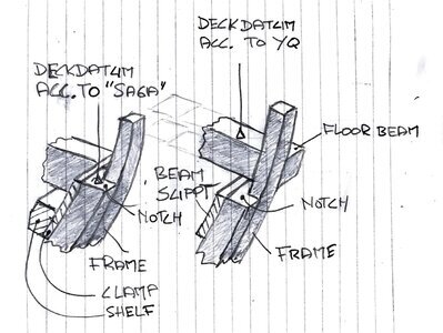
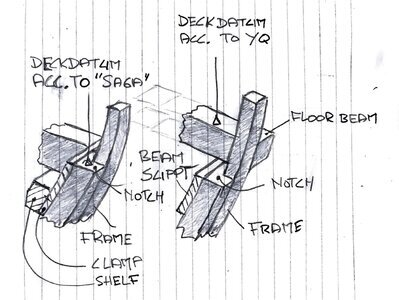
My question has more to do with the different configurations for the floor beam attachment and vertical position, relative to the frame notch. I updated my sketch, in order to clarify what I mean:

F384C218-2EE3-48BB-96A8-87EFD446EA21.jpeg

If you take the notch as the deck's reference datum, which, if I understand correctly, is the underside of the deck for the "big" Bluenose, than YQ, relatively to the notch in the frame, raised the deck's reference datum by the thickness of the floorbeam.
I am not suggesting that the results of our builds are affected, but it's more that YQ's design of the deck datum, clamps, shelves, floorbeams etc do not comply with the "big" Bluenose, although, I used the data from the Saga, so I should be careful with that statement...

I hope this clarification makes a little more sense to you.

Kind regards,

Johan
 
Last edited:
Morning Piero, Rich,

Yes, one can find different nomenclatures for parts with the same function, unfortunately, it's something we'll have to live with and sometimes requires us to exercise some patience... In my case, I hope you have patience in spades. ;)
The top surface of the waterways/covering boards need to be flush with the scuppers, no argument there. It's something Peter Voogt (@Peter Voog) already mentioned ánd addressed in his superb build.
My question has more to do with the different configurations for the floor beam attachmentsand vertical position, relative to the frame notch. I updated my sketch, in order to clarify what I mean:

View attachment 289717

If you take the notch as the deck's reference datum, which, if I understand correctly, is the underside of the deck for the "big" Bluenose, than YQ, relatively to the notch in the frame, raised the deck's reference datum by the thickness of the floorbeam.
I am not suggesting that the results of our builds are affected, but it's more that YQ's design of the deck datum, clamps, shelves, floorbeams etc do not comply with the "big" Bluenose, although, I used the data from the Saga, so I should be careful with that statement...

I hope this clarification makes a little more sense to you.

Kind regards,

Johan
Correct, Johan. YQ uses the notches only as a aligment for the bearing beams (Beam supports).
In the Saga it carries the outside parts of the waterways, as Rich correctly mentioned. As in the Sage: “.... cut to fit around the stanctions.”
Regards, Peter
 
Last edited:
View attachment 289723
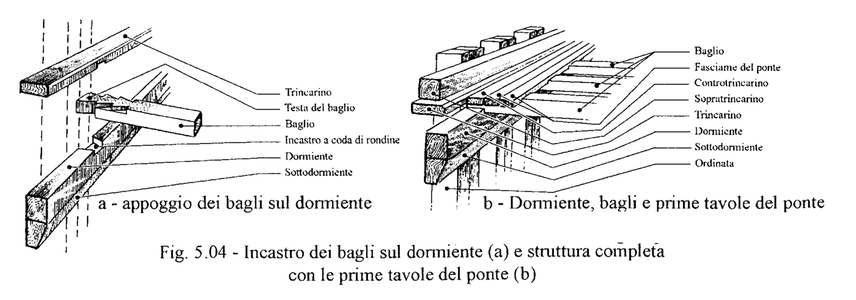
Good morning, did I understand correctly?
Good morning Frank,

Unfortunately my Italian is non-existent, so it's not easily understood, but it is indeed the area of my confusion. The picture you show is not exactly the Bluenose configuration, but it ís the connection of the beams to the shelves, or sleepers as they are called in your picture.
My confusion was more in relation to position of the beams and shelves in relation to the notch of the frames.
Nice, but labor intensive beam-to-shelf connection with the dovetails...

Buongiorno Frank,

Purtroppo il mio italiano è inesistente, quindi non è facilmente comprensibile, ma è davvero l'area della mia confusione. L'immagine che mostri non è esattamente la configurazione Bluenose, ma è il collegamento delle travi agli scaffali o delle traversine come vengono chiamate nella tua foto.

La mia confusione era più in relazione alla posizione delle travi e dei ripiani in relazione alla tacca dei telai.

Bello, ma laborioso collegamento fascio-a-shelf con le code di rondine...

Johan
Good morning RDN, certainly not Blunose, I was trying to help in some way on the carpentry
 
Back
Top