Gorgeous job! Interesting to observe. 
-

Win a Free Custom Engraved Brass Coin!!!
As a way to introduce our brass coins to the community, we will raffle off a free coin during the month of August. Follow link ABOVE for instructions for entering.
-

PRE-ORDER SHIPS IN SCALE TODAY!
The beloved Ships in Scale Magazine is back and charting a new course for 2026!
Discover new skills, new techniques, and new inspirations in every issue.
NOTE THAT OUR FIRST ISSUE WILL BE JAN/FEB 2026
You are using an out of date browser. It may not display this or other websites correctly.
You should upgrade or use an alternative browser.
You should upgrade or use an alternative browser.
BALDER, Vlaardingen Herring Lugger from 1912, scratch build scale 1:50 Plate-On-Frame
- Thread starter Peter Voogt
- Start date
- Watchers 65
Thanks, Sergey. It is a journey of discovery that I like to share with all of you.Gorgeous job! Interesting to observe.
Regards, Peter
- Joined
- Apr 20, 2020
- Messages
- 6,245
- Points
- 738

Dear PeterThe next step I could make was the 6th row of hull plates:
View attachment 521002
Started at the front with the 1st plate that moves slightly outwards. Then 4 plates that are increasingly positioned slightly more upright until just past the middle. Then 3 plates that move further outwards and form the overhang of the aft ship.
View attachment 521003
To be on the safe side, let the plates protrude 2 mm above the outer corner line where the bulwark plates are attached.
I cannot yet glue this row and start working on the bulwark. First, 6 scuppers have to be made in this row:
View attachment 521004
There are 6 holes in the waterways for this purpose with 90 degree pipes that drain to the side.
The photo also shows 2 of the 3 valves that are in the bulwark. These will be done later when cutting the bulwark plates to size.
First placed these 6 tubes in the construction starboard side part:
View attachment 521042
With the corresponding holes in the waterways:
View attachment 521043
Based on the dimensions I could now drill the holes in the plates of the 6th row:
View attachment 521007
Then I can now place the (parts of) the tubes on the inside of these plates and the waterway.
All in all, I have to think very carefully about which parts to apply at which step.
Regards, Peter
as usual, you are doing magnificent work!!!
the pictures the tour in Normandy was interesting & Beautiful
Thanks, Shota.Dear Peter
as usual, you are doing magnificent work!!!
It is a constant search next to the right material for the part in question.
The beaches of Normandy and the fields of Flanders have made a great impression.the pictures the tour in Normandy was interesting & Beautiful
Regards, Peter
These hull plates add the "skin" to your wonderfully executed "bones"!!
It looks to me that it is an extremely difficult, delicate and painstaking process.
You seem to be both inventing and mastering it at the same time. Impressive, as we have all come to expect.
Thanks for the wonderful pictures and writeup!!
It looks to me that it is an extremely difficult, delicate and painstaking process.
You seem to be both inventing and mastering it at the same time. Impressive, as we have all come to expect.
Thanks for the wonderful pictures and writeup!!
Thanks for this compliments and nice words, Brad. Attaching the hull plates is a bit nerve-wracking. Ones glued there is no way back. I could sand and cut the outside of the frames a bit but they kept there Evergreen flexibility. And I could fill up some a bit back laying frames. Then you talk about filling up with strips of 0,15 / 0,25 mm thickness.These hull plates add the "skin" to your wonderfully executed "bones"!!
It looks to me that it is an extremely difficult, delicate and painstaking process.
You seem to be both inventing and mastering it at the same time. Impressive, as we have all come to expect.
Thanks for the wonderful pictures and writeup!!
Luckily for me: the hull of the original Balder is also not perfectly smooth. Most of the time it’s a strive the get a ‘perfect’ hull. But for shure …. this one won’t be perfect ……
Regards, Peter
- Joined
- Jun 17, 2021
- Messages
- 3,202
- Points
- 588

That buckling or "canning " of the plates is more realistic (as your photos of the actual "Balder" reveal). I would regard it as a win. Any photo of an actual steel navy ship, or steel hulled ship reveals the same effect.Thanks for this compliments and nice words, Brad. Attaching the hull plates is a bit nerve-wracking. Ones glued there is no way back. I could sand and cut the outside of the frames a bit but they kept there Evergreen flexibility. And I could fill up some a bit back laying frames. Then you talk about filling up with strips of 0,15 / 0,25 mm thickness.
Luckily for me: the hull of the original Balder is also not perfectly smooth. Most of the time it’s a strive the get a ‘perfect’ hull. But for shure …. this one won’t be perfect ……
Regards, Peter
You are right, Pete. Since I started working with the plates, I seem to look at plated hulls with 'different eyes'.That buckling or "canning " of the plates is more realistic (as your photos of the actual "Balder" reveal). I would regard it as a win. Any photo of an actual steel navy ship, or steel hulled ship reveals the same effect.
In heavy seas, a pitching ship experiences heavy forces pounding on its hull.
Regards, Peter
Thanks for the compliments, Ken.Catching up, Peter, I have to echo what others have said, her hull lines are sleek and beautiful. A very interesting build. Wonderful work!
Regards, Peter
Wow Peter, what a progress again.
I like the slightly dented plating of the hull, these were work horses so some derts would be very reasonable.
I like the slightly dented plating of the hull, these were work horses so some derts would be very reasonable.
Thanks, Maarten. Like the others above: I fully agree about the dented plates.Wow Peter, what a progress again.
I like the slightly dented plating of the hull, these were work horses so some derts would be very reasonable.
Regards, Peter
Last edited:
Another “wow” Peter, I’m just playing catch up with the last few weeks of your stunning build. Beautiful and meticulous work, just beautiful.
Thanks for the compliments and the wow, Roger.Another “wow” Peter, I’m just playing catch up with the last few weeks of your stunning build. Beautiful and meticulous work, just beautiful.
Regards, Peter
Last edited:
WOW, this is an impressive Work of ART,
It took me some time to catch up on your build, but WOW it was worth it.
It took me some time to catch up on your build, but WOW it was worth it.
You also thanks for the compliments and the wow, PeterWOW, this is an impressive Work of ART,
It took me some time to catch up on your build, but WOW it was worth it.
Regards, Peter
Not much to show. Where I have arrived now takes a lot of time to get the lines right.
After gluing the 6th row, it was now the turn of the 1st plate of the bulwark:
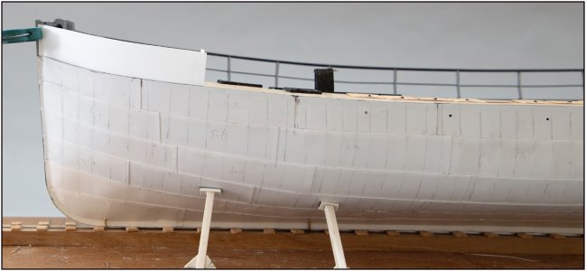
I have to take into account various curves:
-the sheer and the outer curve of the deck;
-the upper handrail that protrudes outside the deck due to the sloping course of the plating, but is different everywhere.
That is almost extreme on the aft ship. That is why I started again at the front.
Then I also have to make sure that it runs parallel to the handrail that I have already placed on the starboard part.
It took me 5 paper templates before I had all the lines running neatly.
This gives a good idea of the various curves:
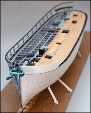
The upper point at the back of the 1st plate bends a bit too much outwards. That is due to the twisting of the plate. When I have the 2nd plate I can also set this one properly. It’s dry-fitted with only a small stroke of tape on the inside where it stands on the waterway.
From another angle:
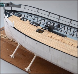
From almost standing up at the bow to the slope in the curve.
With the clear sheer and curve:
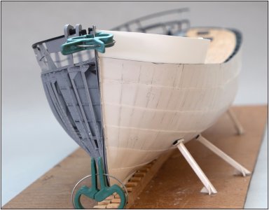
Hopefully the next plates will go a bit faster.
Regards, Peter
After gluing the 6th row, it was now the turn of the 1st plate of the bulwark:

I have to take into account various curves:
-the sheer and the outer curve of the deck;
-the upper handrail that protrudes outside the deck due to the sloping course of the plating, but is different everywhere.
That is almost extreme on the aft ship. That is why I started again at the front.
Then I also have to make sure that it runs parallel to the handrail that I have already placed on the starboard part.
It took me 5 paper templates before I had all the lines running neatly.
This gives a good idea of the various curves:

The upper point at the back of the 1st plate bends a bit too much outwards. That is due to the twisting of the plate. When I have the 2nd plate I can also set this one properly. It’s dry-fitted with only a small stroke of tape on the inside where it stands on the waterway.
From another angle:

From almost standing up at the bow to the slope in the curve.
With the clear sheer and curve:

Hopefully the next plates will go a bit faster.
Regards, Peter
Last edited:
Looking great Peter! Quick question, would it not be beneficial to first add the same structure as the starboard side prior to adding the plates on the bulwarks?
Thanks, Dean. Also for thinking with me.Looking great Peter! Quick question, would it not be beneficial to first add the same structure as the starboard side prior to adding the plates on the bulwarks?

I also use the structure to estimate the size of the plates. But not the exact size because fitting a plate between the parts is almost impossible. All the plates have curves. In the middle only lengthwise but in the front and aft in more directions. An explanation using this earlier drawing:
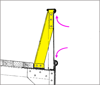
To set the plate in the already stand structure, I have to fold the curved plates from the outside (blue arrows) against the inside of the handrail and top plate. From the inside it is not possible because of the support (yellow) with the small corner support on top. The supports are pushing from the side against the plates. And then there must be on the inside of the handrail a gap of 0,25 mm for the plate with the small corner support.
I also considered sliding them in but my plan is to first apply the 4 flaps to the plates before installing them:
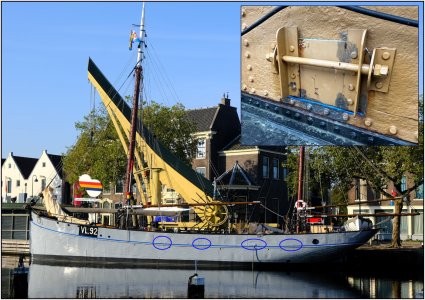
These are flaps of 7 x 5 mm ...... and of course they must be hinged…...
Then my intention is also to spray the plates in color first before installation because masking them off inside is almost impossible.
So I've been reasoning for quite some time about the right order of all the steps. And honestly ...... I haven't fully convinced myself yet what is right. But that's actually been the case throughout the entire build.
Regards, Peter
Last edited:
I see, then I would add the lower corner support (angle iron) first (that the plate is above), then the plate, then the yellow braces and their mounting plates, and finally the handrail last. So it looks like you are working in the correct order.Thanks, Dean. Also for thinking with me.
I also use the structure to estimate the size of the plates. But not the exact size because fitting a plate between the parts is almost impossible. All the plates have curves. In the middle only lengthwise but in the front and aft in more directions. An explanation using this earlier drawing:
View attachment 522156
To set the plate in the already stand structure, I have to fold the curved plates from the outside (blue arrows) against the inside of the handrail and top plate. From the inside it is not possible because of the support (yellow) with the small corner support on top. The supports are pushing from the side against the plates. And then there must be on the inside of the handrail a gap of 0,25 mm for the plate with the small corner support.
I also considered sliding them in but my plan is to first apply the 4 flaps to the plates before installing them:
View attachment 522163
These are flaps of 7 x 5 mm ...... and of course they must be hinged…...
Then my intention is also to spray the plates in color first before installation because masking them off inside is almost impossible.
So I've been reasoning for quite some time about the right order of all the steps. And honestly ...... I haven't fully convinced myself yet what is right. But that's actually been the case throughout the entire build.
Regards, Peter


