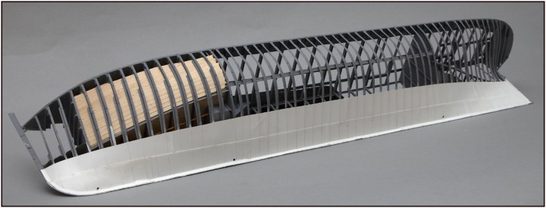
Now I have arrived at what was already on my mind during the entire build:
will plating the frames result in a tight hull?
Thanks to the earlier alignment of the rows of plates:
View attachment 520509
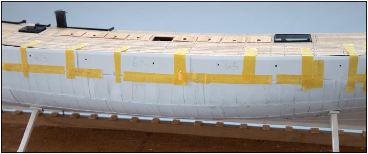
I was able to apply the next 3 rows quite quickly.
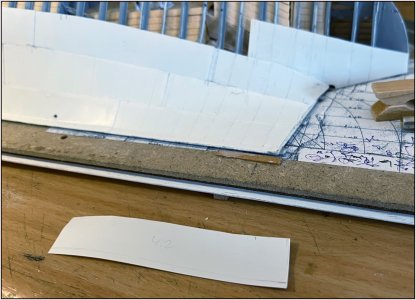
I had already applied 2 rows with 005"/0.13 mm plate:
View attachment 520510
But the thin material is counterproductive, especially in the places where the hull goes from concave to convex. I then have to work the plate on 2 sides, which is roughly the same as forcing copper plate:
View attachment 520511
The thin material does not retain its shape but goes its own way with further deformation. When gluing, the surface also melts a little, which in this case also promotes further deformation. This was already clearly visible in the first 2 rows where the curvature of the shapes was not yet very strong.
That is why I switched to 010"/0.25 mm plate. This was much easier to deform.
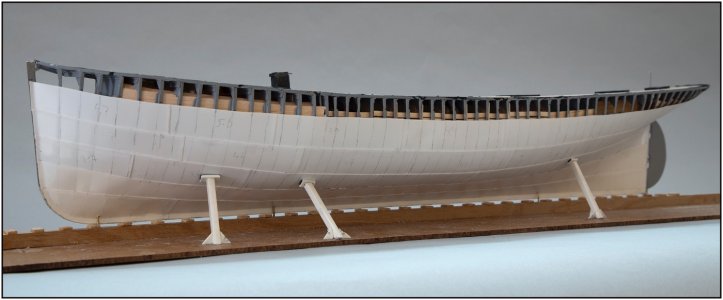
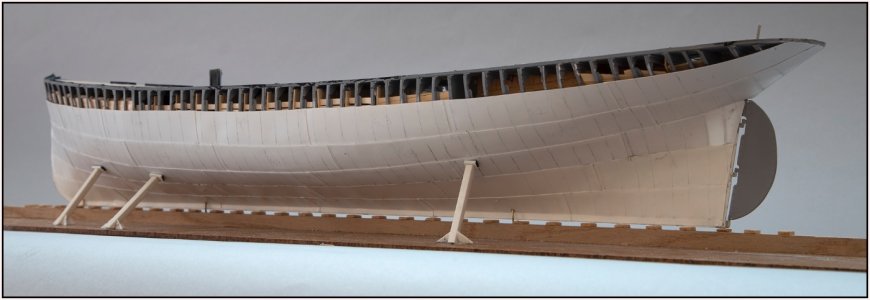
Then this is the rough result so far:
View attachment 520512
Now still in bright over-shining white, but with a little subdued light the contours come out nicely.
View attachment 520513
View attachment 520514
On the plates I have marked the position of the frames. Vertical rows of rivets should come there. I just have to test whether I first spray a base coat and then stick the rivets. Which gives the best adhesion of the rivet decals. I have to stick the waterline to make the transition from black to light blue. Maybe the pencil lines will remain visible with a thin base coat.
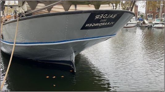
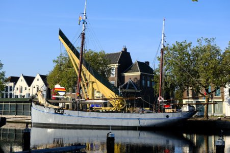
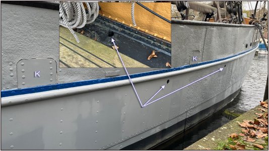
The plating on the back has a specific gradient. Here is the original:
View attachment 520515
I had to mirror it to be able to compare the visible starboard side with my port side.
A brief explanation of the next step:
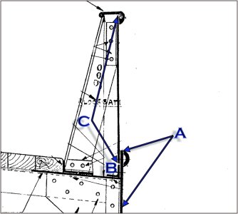
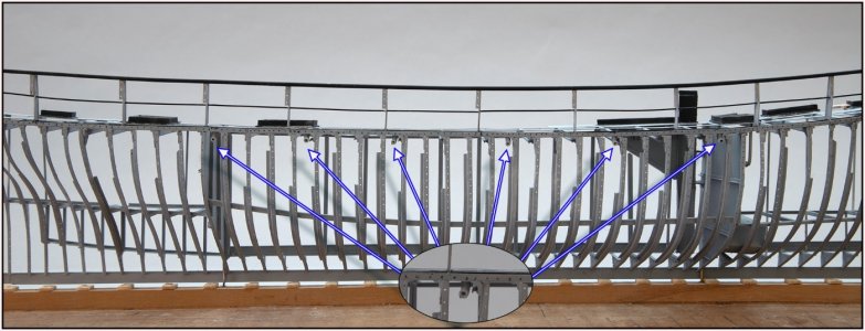
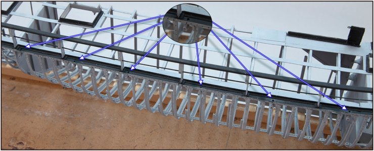
I now have to make the 6th row very precisely to size in order to be able to attach the bulwark to it:
View attachment 520516
The 6th row (A) must protrude 1.6 mm above the outer angle iron (B) of the waterway. The plate for the bulwark (C) is on top of it, on the inside of the 6th row.
There are then 2 rows of rivets over the entire length. Skin plate A has a connection with angle iron B and bulwark plate C is attached to the top of skin plate A. At the top of the 6th skin plate, the connection with the bottom of the bulwark plate is covered with a half-round bumper.
Regards, Peter


