• LUCZORAMA SHIPWRECK SCAVENGER HUNT GIVEAWAY. 4 Weeks of Fun • 1 Legendary Prize ((OcCre’s Fram Ship)) • Global Crew Welcome!
    **VIEW THREAD HERE**

HMS ENTERPRISE 1774 by RichardJJS 1:48 scale. New Kit from M.D

Not sure if you are talking Stern or Frames

But its bit late now its all stuck
Note ive still got to lift the upper frames in and ive moved 04 (second picture ) down slighly so it lines up with the dashes

Its also too late for the stern as its also glued up

Could have given me a clue as i will not be able to sleep
The stern section looks Ok, it's the frame. Zooming in on your photos, I see that you have put the wrong chocks in. Also you are offsetting the pieces. Each piece or futtock should be directly over the drawing for both A and B side. They fit exactly over their place on the drawing. The line in the chock is the sanding line and should correspond with the sanding line on the pieces each side of the chock, it is not the outside edge, so you have glued the chock meant to go on side B on side A. Every chock has it's own place. Also I didn't say NOT to sand the char at the joints but just be careful not to take too much off that you change the shape of the joint surfaces. You have to clean also the surfaces that butt on to the keel. I have to go out now. Do you want me to go through the make up of a complete frame when I get home later or are you OK with it? This kit is very detailed and so quite complex, certainly the most difficult of the ones I have made. You have to concentrate and have an idea of what you're doing
 
Not sure if you are talking Stern or Frames

But its bit late now its all stuck
Note ive still got to lift the upper frames in and ive moved 04 (second picture ) down slighly so it lines up with the dashes

Its also too late for the stern as its also glued up

Could have given me a clue as i will not be able to sleep
I like to keep my evenings free to relax so not going to spend time on lengthy messages
 
@richardjjs you never answered my question to you on Keef's thread of which glue you are using other than "titebond".
Depending on the glue, there are different ways of "debonding" the glue so you can take it apart without much damage to the parts.
 
I dont think i explained properly what i am now doing
I found that when i built a full frame parts move so
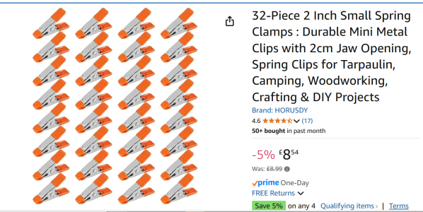
a) I got these new clamps (to me) from Amazon
I then do 1 joint each side putting a set i 1mm spare pieces under when needed build
Usually the top 2 pieces are actually the same size so those I build flat and join lifting them after they are dry with the spare pieces
Using Titebound with the clamps now works really well and ive had no movement
I did post a picture with the lower part of no 4 slightly too high and when i put down the upper row it was obvious (Now Corrected)
Sorry if i confused
Note the spare pieces ready to lift the upper parts
REally cant recommend the clamps better

IMG_20250705_092928[1].jpg

Clamps.png
 
Last edited:
The stern section looks Ok, it's the frame. Zooming in on your photos, I see that you have put the wrong chocks in. Also you are offsetting the pieces. Each piece or futtock should be directly over the drawing for both A and B side. They fit exactly over their place on the drawing. The line in the chock is the sanding line and should correspond with the sanding line on the pieces each side of the chock, it is not the outside edge, so you have glued the chock meant to go on side B on side A. Every chock has it's own place. Also I didn't say NOT to sand the char at the joints but just be careful not to take too much off that you change the shape of the joint surfaces. You have to clean also the surfaces that butt on to the keel. I have to go out now. Do you want me to go through the make up of a complete frame when I get home later or are you OK with it? This kit is very detailed and so quite complex, certainly the most difficult of the ones I have made. You have to concentrate and have an idea of what you're doing
Sorry missed you reply
Did move that lower frame part into the correct place
Yes the Chock was wrong - to late as ive glued
Will triple check them in future !!
MUST try harder but thanks
 
I am using Titebond Original Wood Glue Seems OK now ive got the new Clamps
The Superglue i use is ZAP CA or Thick
Also UK type Thin and MEdium
But thanks

when you do Frame Y8 it finishes at the lower part It gives support to the Sterm Frame


Thanks
 
Last edited:
I am using Titebond Original Wood Glue Seems OK now ive got the new Clamps
The Superglue i use is ZAP CA or Thick
Also UK type Thin and MEdium
But thanks
Just a question

Can you look at Y8 Frame
it looks as though One of them has Not top frames as it finished with a Cut Off - Maybe a rear support for something

Thanks
The Titebond wood glue (which is a form of PVA glue) can be disassembled with heat. You can use a heat gun or in some cases even a hair dryer to loosen the glue for disassembly. For the CA type glues, there is a de-bonder available on the market or you can use acetone. It takes time, but it will work. The vast majority of us have needed to unglue parts we have installed. :)

As far as the Y8 frame, it looks like the A side half is only half high and has part F2-5 (a transom piece) attached to the top of it. It is shown pretty well in step 36 of the instructions. It's also shown well in step 31. Always do lots of trial fitting before using glue. :)
 
yes got that
Been using Superglue for Years - In fact I distributed it through my MOdel Distribution Business where i ran 3 Vans Covering the UK in the 90's But Didnt know about PVA will dig my SolarFolm shrink gun out !!
 
The stern section looks Ok, it's the frame. Zooming in on your photos, I see that you have put the wrong chocks in. Also you are offsetting the pieces. Each piece or futtock should be directly over the drawing for both A and B side. They fit exactly over their place on the drawing. The line in the chock is the sanding line and should correspond with the sanding line on the pieces each side of the chock, it is not the outside edge, so you have glued the chock meant to go on side B on side A. Every chock has it's own place. Also I didn't say NOT to sand the char at the joints but just be careful not to take too much off that you change the shape of the joint surfaces. You have to clean also the surfaces that butt on to the keel. I have to go out now. Do you want me to go through the make up of a complete frame when I get home later or are you OK with it? This kit is very detailed and so quite complex, certainly the most difficult of the ones I have made. You have to concentrate and have an idea of what you're doing
Can you do me a Frame Build please
Thought id cracked it but it still seems to be moving
I thought i knew what i was doing but ......
I clamp them down and its seem to MOVE
It was me who said about removing Char (But will lightly remove it
Just trying some superglue on a frame
THANKS
 
Last edited:
Can you do me a Frame Build please
Thought id cracked it but it still seems to be moving
I thought i knew what i was doing but ......
I clamp them down and its seem to MOVE
It was me who said about removing Char (But will lightly remove it
Just trying some superglue on a frame
THANKS
I will help you, but I can't spend a lot of time until a couple of days, lots of things happening here at the moment. All I can say at the moment is Superglue is not good to use for the frames . A good PVA is the best, and really the only glue to use. I do not use clamps either as they put pressure on the joints, especially curved ones, and if the joints are loose will cause them to move slightly. Look at the early pages of my build log relating to the make up of the frames. When I make the frames, l spend time locating and identifying the parts and removing them from the sheets. Securely tape the correct drawing to a flat hard surface. I use a kitchen cutting board. Then put a small strip of transparent tape covering the areas on the drawing where the joints for the chocks and scarf joints are. This way the pieces can be placed and glued directly over the drawing and when any glue dries, it does not stick to the paper. The page is not damaged so can be used again for the next side A or B. Carefully, very lightly clean all the joints and chocks as well as the surfaces which will join onto the keel. I use a fine needle file rather than sanding sticks as you get a flatter finish. Just take off the worst of the char, not down to bare wood. the surfaces should still be discolored so as not to risk changing the shape of chocks or scarf joints. Make sure you know where and which way the steps in the frames are by checking with the diagrams in the manual for each frame. Check again, then before gluing check again.

WILL CONTINUE THIS TOMORROW
 
That is great
Ive been using a Cork Board and using pins to guide it
Will look at a straight build on a hard surface so if that is better
I have been using TiteBond
Just out of interest
02 with the long upper part is THicker than the lower one - JUst doesnt seem right
But will LATER check to make sure ive got the right part
I don't see a part labeled O2 and I looked throughout the entire instructions and don''t see an O2, so I don't know what you are talking about.
 
sorry its frame 02 the top long top part of the front of the frame see photo sent private message
Shows how important it is to use the right terminology
 
sorry its frame 02 the top long top part of the front of the frame see photo sent private message
Shows how important it is to use the right terminology
Oh, it is correct on the plans. You will notice quite a few of them in the build because that piece needs to support one side of a gun port frame. They actually shaped it a little bit on the real ship is in this image. Look at step 26 in the instructions. :)
1751750585877.png
 
just to confirm your Parts (3L & 3R) are 7mm thick

(SAme as 1 & 3R 7 2l)
Si i presume we dont use the 1mm spacers

Bit like me at the moments !
 
Oh, it is correct on the plans. You will notice quite a few of them in the build because that piece needs to support one side of a gun port frame. They actually shaped it a little bit on the real ship is in this image. Look at step 26 in the instructions. :)
View attachment 530272
But if you look at the bottom of the above picture the blue part is thinner the the red one below it
Why is My "Blue" part of the frame 7mm
Will check the other parts on that sheet to se if they are correct (Tomorrow)
But yes I see that on 26 It is wider and it is 7mm
THANKS
 
Back
Top