• LUCZORAMA SHIPWRECK SCAVENGER HUNT GIVEAWAY. 4 Weeks of Fun • 1 Legendary Prize ((OcCre’s Fram Ship)) • Global Crew Welcome!
    **VIEW THREAD HERE**

HMS ENTERPRISE 1774 by RichardJJS 1:48 scale. New Kit from M.D

That is great
Ive been using a Cork Board and using pins to guide it
Will look at a straight build on a hard surface so if that is better
I have been using TiteBond
Just out of interest
02 with the long upper part is THicker than the lower one - JUst doesnt seem right
But will LATER check to make sure ive got the right part
Yes the top timber of frame 2A is 7 mm because it is a gun port frame. You will find this on all the A frame top timbers that are before a gun port.
To continue a bit more of a frame build. After cleaning the char, l place all the pieces of both A and B sides over the drawing to check you have all the right pieces. They will fit exactly to the plan. I start with side A, and glue the chocks on to the floor timber. They are the same thickness. I do this on a flat surface and squeeze the parts together with finger pressure, holding them for a few minutes so they stay together, then carefully transfer the assembly to the drawing and position it exactly over the top. After about 15 minutes you can glue and carefully fit the second futtock in place and hold it there for a few minutes. Be careful not to move the bottom timber assembly. You have to adjust the parts to exactly fit the drawing. Do the same with the top timber until the A side frame is done. Leave the assembly for at least 12 hours. Obviously you will double checked the futtock shift with the frame plans on the manual and used the spacers accordingly!!
Will continue again later. . .
 
Will try all this now

The main difference is that you put the chock on and let it dry before adding the second Futtock

will make sure its all its before gluing
WAiting ..... (!) ;)
 
Hi Keef and Corsair
JUst want to say thank you all the Help
I did build the Blandford and it went really well - till I tried to stain it and the glue made it patchy
I am pedantic in my work and gave up
But yes i do understand about all the parts but as you say Keef this is a different level of Skill
Have done 2 frames the way you say (Well working on it now)
I have done the second one on a Cork Board as I can move it across the Table to dry
I am Lucky have my own Model Room
Hopefullu ONward and Upward
Waiting for a decent Heatgun to do the joints i am not happy with
THANKS
 
Looking at the main plan it "LOOKS" as though the Top Timber frame of 7a is 2mm not 1 mm Would you agree
Should i shape it before fitting
 
Last edited:
Will try all this now

The main difference is that you put the chock on and let it dry before adding the second Futtock

will make sure its all its before gluing
WAiting ..... (!) ;)
Hi Richard, back again.
Once the A side has completely dried (overnight preferably) You can make up the B side in the same way. As all 3 parts are the same thickness (7 mm), I found the floor timber section with the cross chock can be glued on a flat surface, held with finger pressure for a minute or so and let dry for about 15 mins. After this time the assembly should be strong enough to move, so very carefully transfer the assembly onto the drawing and check the angles are correct, you can adjust slightly if needed so that it fits perfectly over the plan. You can add the first chocks on either side at this point as well. Let the parts dry for 45 mins or so, then glue and add the second futtock being careful not to move the parts on the drawing. The top timbers with the scarf joints are both the same thickness so these can be glued together away from the rest, on a flat surface, held together with finger pressure for a minute or so and carefully placed over its position on the drawing to check it fits perfectly with the plan. After 15 mins or so this can the be glued to the rest of the frame, after checking the step up or down and using the spacers as required. Leave the assembly to completely dry. While you're doing all this you can be squaring the chocks at the futtock joint/s as shown in step 21 of the manual and locating and cleaning the parts for the next frame, ready to do the whole thing all over again . . . and again :)
 
When the A and B sides have completely dried and the chocks on both sides squared off where required, they can be lightly sanded and the 2 sides, A and B, can be glued together to complete the frame. This can be a bit awkward (for me anyway with only one hand fully functioning). Check that the faces with the sanding lines etched into them are both facing outwards. You must use 1mm or 2mm spacers in between the 2 sides and glue the floor timbers, joining them together using clamps along the length of the frame. Check and make sure they are both perfectly aligned and the joining surfaces at the base of the floor timber is absolutely correct with a step up between the 2 sides where the complete frame joins to the top of the keel. Leave the complete assembly to completely dry. You're ready now for the sanding to fair the frame.
There's probably other and better ways to make up the frames, but this has worked for me.
 
I think we need a Group Post as was suggested earlier
Adding all this useful information
Got some |Titebond III Ultimate to try
 
Using Titebond Normal
still Correcting Bad Frame but ive built a few and they seem to be sticking well and NOT moving

Working on Keefs suggestions of adding a chock leaving to dry and then adding next Part

Must admit i am using the Cork Board and a few nails as it holds it in place

Will let you know .......
we all develop a method that works for us. :)
 
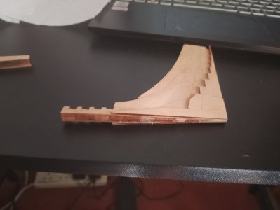
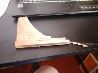
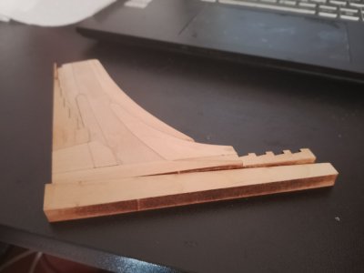
Looking at the Stern assembly
All nicely sanded down but I assume i need to remove G1-8(2) and sand the assembly own a bit so its same as Stern POst
And i presume the Stern post needs sanding down to thatch the Keel assembly

Sorry to ask but better check than ruin another part

IMG_20250708_142242.jpg
 
Looking at the Stern assembly
All nicely sanded down but I assume i need to remove G1-8(2) and sand the assembly own a bit so its same as Stern POst
And i presume the Stern post needs sanding down to thatch the Keel assembly

Sorry to ask but better check than ruin another part

View attachment 530702
Also, I see you are missing the corner piece that goes just above G1-9 and G1-10. They don't show it in step 14 part C, but then it is magically there in step 14 part D. I believe the part number is G1-11.
 
Also, I see you are missing the corner piece that goes just above G1-9 and G1-10. They don't show it in step 14 part C, but then it is magically there in step 14 part D. I believe the part number is G1-11.
will look and add - thanks
but do i need to trim it all down the match the thickness of the keel post - then the keel post to the keel
 
will look and add - thanks
but do i need to trim it all down the match the thickness of the keel post - then the keel post to the keel
I don't believe the keel post (A-13) is trimmed down. I think the planking will butt up against it, but I may be wrong. :)
yes, it appears to remain full width which is the same as the keel. You can see it in step 103. Of course, that is just a picture that someone has drawn. Hopefully they pictured it correctly. :)
 
Looking at the Stern assembly
All nicely sanded down but I assume i need to remove G1-8(2) and sand the assembly own a bit so its same as Stern POst
And i presume the Stern post needs sanding down to thatch the Keel assembly

Sorry to ask but better check than ruin another part

View attachment 530702
The stern post is no sanded at all
Looking at the Stern assembly
All nicely sanded down but I assume i need to remove G1-8(2) and sand the assembly own a bit so its same as Stern POst
And i presume the Stern post needs sanding down to thatch the Keel assembly

Sorry to ask but better check than ruin another part

View attachment 530702
The stern post A13 is not sanded at all. Please look at my build log number 77 shows the stern deadwood assembly.
 
I don't believe the keel post (A-13) is trimmed down. I think the planking will butt up against it, but I may be wrong. :)
yes, it appears to remain full width which is the same as the keel. You can see it in step 103. Of course, that is just a picture that someone has drawn. Hopefully they pictured it correctly. :)
is it step 104
We have cut the bottom part of the Stern to 4mm with G Parts
And the Stern POst is 8mm Maybee check the Rudder
Taking a break as i dont want to cut too much Will look a t everybody's builds #
 
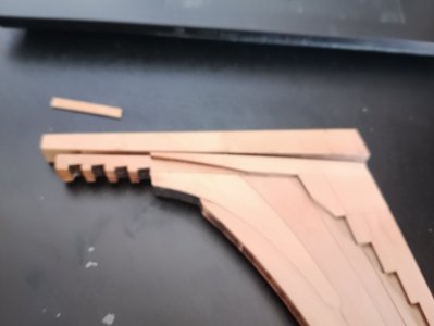
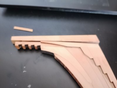
I need to ask a REALLY STUPID question about the Frames
Which way up should the B Futtocks be placed on the Plan
The way they will be built ie Marked side down or marked side up (ie B Futtocks)

only Some of the Frames appear to have totally flat sides on the Main Drawing (around the Gun Ports)

FRAME 1A appears to be totally flat on its Bow side (Front) This is pretty obvious

FRAME 5B appears to be totally flat on its Bow side (Front)
FRAME 6A the top Futtock is forward of the others as explained in the instructions on the Gun Port
FRAME 6B is Flat on the Bow side (Front)

FRAME 9A Not Flat on Bow side (front)
FRAME 9B is Flat on the Bow side (Front)
FRAME 10A LOOKS forward on Front but lines are missing on my drawing
FRAME 10B is Flat on the Bow side (Front)

FRAME 13B is Flat on the Bow side (Front)
FRAME 14B is Flat on the Bow side (Front)

Getting very complicated - ad its only when you have build a few frames it is obvious
The other Gun Port frames are the same but only the Futtock on the back of Gun Port is explained!!
Will look again in the morning BUT!!!
Do i need to send a picture
 

Attachments

Last edited:
Hey Richard,
Here is a link to a video on building the HMS Enterprise by Modelship Dockyard. However, this video is on their 1/96 scale kit so there are some differences, but there is also a lot of similarities. :) Watch it and see if that helps you some. Yes, they have a full series on Youtube. :)
Link to YouTube video
 
Back
Top