- Joined
- Jan 10, 2022
- Messages
- 860
- Points
- 403

Not thought that far ahead yet but more than likelyKeith,
Are you contemplating hawse holes although the kit seems not to provide for them ?
 |
As a way to introduce our brass coins to the community, we will raffle off a free coin during the month of August. Follow link ABOVE for instructions for entering. |
 |
 |
The beloved Ships in Scale Magazine is back and charting a new course for 2026! Discover new skills, new techniques, and new inspirations in every issue. NOTE THAT OUR FIRST ISSUE WILL BE JAN/FEB 2026 |
 |

Not thought that far ahead yet but more than likelyKeith,
Are you contemplating hawse holes although the kit seems not to provide for them ?

That is brilliant - ThanksAs
This framing is more like on Admiralty models than the actual ships so go with whatever works best. Even on the actual ships there were spacers at times, and the size of the spacers varied all over the place even on the same ship as the frames were set up to form the gun ports. Below example is Vengeance 1774. You can see the pieces between frames varies a lot as the siding of the frames varies from the floors to the top timbers. These spacers are only on the station lines but I have no idea why.
Allan
View attachment 534232
On the diagramComing along with the construction of the hawse pieces. x8A and B have been faired. x8B is in its position on the keel, while x8A is placed in the jig for the hawse pieces as all the frames will attach to it. The first piece, F1 is sanded to shape, inside and out. This is the piece that attaches vertically to the hull and is the longest of the 7 frames making up the hawse pieces. It is dry fitted to the cant frame x8A and fits very nicely. F2 is also sanded to shape and takes up its position in the jig next to F1. I must be doing something right as it fits on x8A and the shape forming is instantly recognizable. All good so far
View attachment 533450
View attachment 533451
View attachment 533452
View attachment 533453
View attachment 533454
View attachment 533455
View attachment 533456
View attachment 533457
On the diagram HAWSE PIECES it says "Attaching to surface Y8" I presume it means X8B !Coming along with the construction of the hawse pieces. x8A and B have been faired. x8B is in its position on the keel, while x8A is placed in the jig for the hawse pieces as all the frames will attach to it. The first piece, F1 is sanded to shape, inside and out. This is the piece that attaches vertically to the hull and is the longest of the 7 frames making up the hawse pieces. It is dry fitted to the cant frame x8A and fits very nicely. F2 is also sanded to shape and takes up its position in the jig next to F1. I must be doing something right as it fits on x8A and the shape forming is instantly recognizable. All good so far
View attachment 533450
View attachment 533451
View attachment 533452
View attachment 533453
View attachment 533454
View attachment 533455
View attachment 533456
View attachment 533457

I used a modelling drum sanded to remove the worse of the Char and Stuff that needed sanding down then Finished of with a hand held sander . Seems OK But before i glue it all in will finly sand it to gicve a clean fiishThat is a fine choice.Myself, I’ve used the 2”drum with 180,
Don’t touch frames until paired and I then hold the paired frames frreehand off the table to bevel inside and out. Using the lines and char allows you to keep things nice and even. 5 minutes to bevel a full frame,
Tip: as you progress, take the bevels right down to the lines, without knowing exactly what my margin for error might be I left several just off the line but that resulted in more sanding……those lines are accurate.
My images show this result so you be the judge on process.
One of the reasons I asked was about your small spacers.Not thought that far ahead yet but more than likely

Yes Ive just checked mine - need break for FRAMESThat is brilliant - Thanks
On the diagram
On the diagram HAWSE PIECES it says "Attaching to surface Y8" I presume it means X8A !

No. x8A is correct. x8B is on the stern side as it is with all the frames. y8 is for the stern can't framesThat is brilliant - Thanks
On the diagram
On the diagram HAWSE PIECES it says "Attaching to surface Y8" I presume it means X8B !

The instruction quote Y8No. x8A is correct. x8B is on the stern side as it is with all the frames. y8 is for the stern can't frames

My instructions don't say anything about y8The instruction quote Y8
THats what i Mean Its Wrong

its on the Printed White Page Hawse Pieces Bottom Left - Attach to Y8 !!My instructions don't say anything about y8

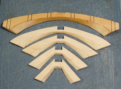
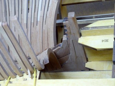
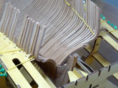
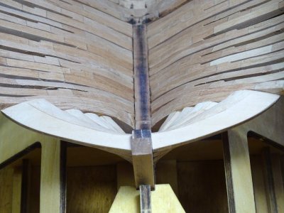
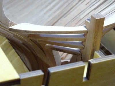
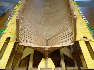
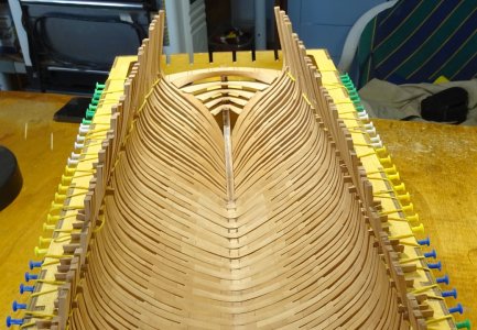
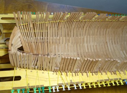
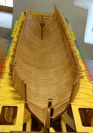
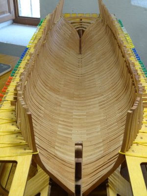
Looking good Keith- nice oneAll the hull frames are complete and permanently fixed onto the keel, making a complete hull, except for the hawse piece assemblies, port and stbd., which are still awaiting my small repair work-in-progress. In the meantime, I have moved on to the transom. The 5 pieces are shown after sanding to shape. They attach to frame y8B and the stern post. A bit of fine tuning is involved in getting them to fit and they are very awkward to get at whilst in the jig but worked out OK in the end. btw. Almost forgot. Be aware, to achieve the angle for the cant frame y8, you must ignore the sanding line lasered onto the floor timber of y8A. This looks to be a manufacturing error
View attachment 535824
View attachment 535825
View attachment 535826
View attachment 535827
View attachment 535828
View attachment 535829
View attachment 535830
View attachment 535831
View attachment 535832
View attachment 535833
It’s always a complex part of the hull, Keith. It’s looking very nice.All the hull frames are complete and permanently fixed onto the keel, making a complete hull, except for the hawse piece assemblies, port and stbd., which are still awaiting my small repair work-in-progress. In the meantime, I have moved on to the transom. The 5 pieces are shown after sanding to shape. They attach to frame y8B and the stern post. A bit of fine tuning is involved in getting them to fit and they are very awkward to get at whilst in the jig but worked out OK in the end. btw. Almost forgot. Be aware, to achieve the angle for the cant frame y8, you must ignore the sanding line lasered onto the floor timber of y8A. This looks to be a manufacturing error
View attachment 535824
View attachment 535825
View attachment 535826
View attachment 535827
View attachment 535828
View attachment 535829
View attachment 535830
View attachment 535831
View attachment 535832
View attachment 535833

Thanks Peter. It sure is difficultIt’s always a complex part of the hull, Keith. It’s looking very nice.
Gr. Peter

That´s another way of doing itKeith,
Looks like they turned out nice.
When I did mine, for others reference, I did them absent the last couple cant frames to get the ends to butt up against frame as evenly as I could………a bit less fidgety.
Tim
Cheers my friendLooking good Keith- nice one

Cheers Grant. All the bestLooking good Keith- nice one


just rechecking what you have done so farThanks very much Jeff. I am indeed counting this as a mile stone in the construction of this build. Everything fits so nicely in a tribute to the design and manufacture of this kit. Excellent job Modelship Dockyard!! The next step is the construction of the cant frames x1 to 8 (bow) and y1 to 8 (stern). Although first I think I shall glue all the these frames to the keel. A little daunting as this would then be permanent, but it has to be done at some point.
View attachment 528655
View attachment 528656
View attachment 528657
View attachment 528658
View attachment 528659
View attachment 528660
View attachment 528661
View attachment 528662
View attachment 528663
View attachment 528664
View attachment 528665

A couple of questions about this so farNow all the midship frames are complete (1 to 37), these are the frames attached to the keel at 90 degrees, the next thing is to concentrate on the cant frames (x1 to x8 at the bow and y1 to y8 at the stern). They are set at an angle to the keel hence the name cant frames and require an entirely different approach. Unlike the 'straight' frames which are one piece made up of an A and B side, these are 2 separate units of A and B glued either side of the bow or stern deadwood. Also, to make things even more complicated, every other (the even numbered units) are not glued together at the floor timbers, but the A and B sides are to be treated as separate, i.e. not glued together. Each set of frames sit in the support notches either side of the deadwood which were made when the keel was first constructed. Attention must be taken to get the angle correct where the frames join the keel. This angle gets steeper the closer to the bow (or stern). So far all frames are dry fitted. A little fine tuning will be necessary when it comes to gluing everything permanently into place.
View attachment 529243
View attachment 529244
View attachment 529245
View attachment 529246
View attachment 529247
View attachment 529248
View attachment 529249
View attachment 529250
View attachment 529251
View attachment 529252
View attachment 529253
View attachment 529254
View attachment 529255
View attachment 529256
View attachment 529257
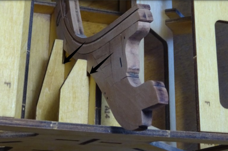

Getting Close to this stage This is incredible work from you !!Have now completed the fore cant frames (x1 to x7). There is actually an x8 but I am leaving that for the time being as x8A is used to make up the hawse pieces and is not fitted into the hull until that part is complete. Everything is still only dry fit and some work is required on the cant frame bases where they join the hull as some of the angles are not quite right. Not too bad but could be better. So, I think next I shall permanently fix the frames 1 to 37 to the hull, the concentrate on the stern cants
View attachment 530371
View attachment 530372
View attachment 530373
View attachment 530374
View attachment 530375
View attachment 530376
View attachment 530377
View attachment 530378
View attachment 530379
View attachment 530380
View attachment 530381

Thanks Richard. Good I can be of some help. No problems with the frames at all. They all fit exactly as they should. When you get to the cant frames take great care to get the angles right where they meet the deadwoodjust rechecking what you have done so far
Brilliant not only in your work but helping me
I did put temp separators in between the frames but like the idea of them all being at the same level and sticking out
Did you find any problems after you had glued these frames in ?
Again thanks
