- Joined
- Mar 20, 2026
- Messages
- 55
- Points
- 78

Great Work!Building the Display Base
For my display base, I was inspired by Peter Davies-Garner’s book, “RMS Titanic: A Model Maker’s Manual”. In it, he states:
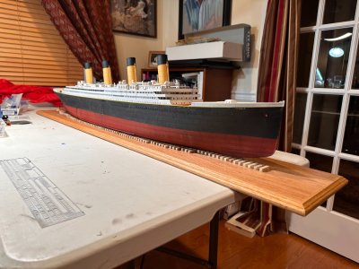
I chose an oak plank which I cut to 5’ (153cm) in length and added molding on all sides. I finished it with tung oil.
View attachment 617021View attachment 617018
I used a track saw to cut the oak board to length. A regular circular saw would’ve been fine, but I wanted to make sure that my corners were perfectly square so that my trim miters would look clean.
View attachment 617020View attachment 617017View attachment 617023
Lot’s of sanding: 60g/120g/220g/320g to make it smoooth. I like Osmo Polyx-Oil for projects like this. It wipes on with a cloth and preserves the feel of the oak.
View attachment 617022View attachment 617014
I taped several blank sheets of paper together to trace the shape of the hull, which I reduced to groups of strip lengths. Using the template, I marked out the locations for each strip length on the oak board. The strips (“blocks”) were made from 1/4” (7cm) poplar and cut to length using a small miter saw. Each was glued to the base using Gorilla wood glue and spaced using a scrap strip as a spacer.
View attachment 617008
Eventually, after much cutting and gluing, you get something like this.
Mounting the Hull on the Base
The hull was attached to the base using three (3) No 8, brass wood screws. One screw is amidships with the other two spaced 10” forward and 10” aft, along the centerline.
View attachment 617010
I inserted a short strip in the space between the mounted strips to provide mounting points for the hull and to drill the pilot hole through from the top. This helped later to locate the hole when I drilled another pilot hull from beneath up into the hull and countersunk the hole.
View attachment 617009
The model was carefully centered fore and aft and left to right on the base. I then held it in place using painter’s tape and a 25lb dumbbell. This arrangement kept things steady while I drilled pilot holes up into the hull from the bottom and then drove the screws.
View attachment 617024
One of the brass, counter-sunk screws holding the model to the base.
View attachment 617011View attachment 617013
I’m satisfied with the result. Now that the model is mounted, I can proceed with installing the propellers and the boat deck structures. Of course, moving now involves carrying the entire base and ship assembly, but at least the model has more protection.
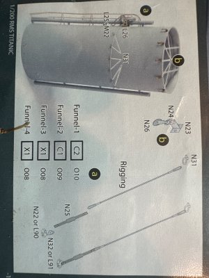
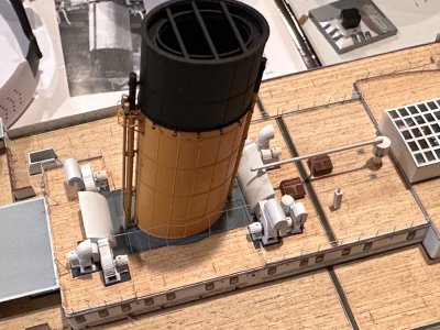
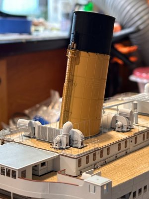
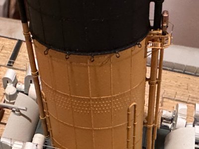
With the 3D printed funnels, are you going to drill in holes from the stays?
The drydock method looks great on your Titanic. Its the same plan I will use on my 1:350 Titanic when I get to that point. I haven't thought about the layout yet, but your method looks great and I will probably use it when I get there. Thank you for the inspiration on you build
Pete