• Win a Free Custom Engraved Brass Coin!!!
    As a way to introduce our brass coins to the community, we will raffle off a free coin during the month of August. Follow link ABOVE for instructions for entering.

HMS Victory of Caldercraft by Wil

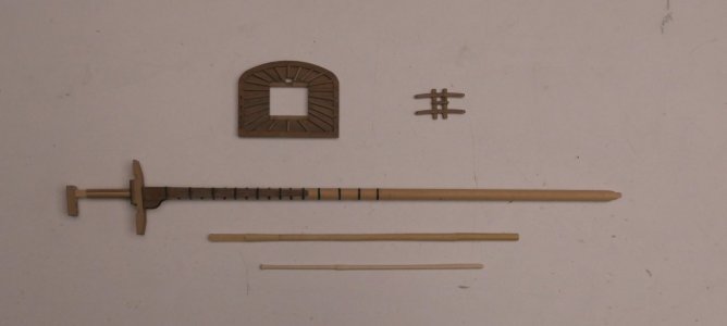
30 Making Mast Components

Meanwhile, I’ve started looking into the masts and rigging. There are still quite a few challenges here, like the mizzen topgallant yard, which needs to taper over 49.5 mm from 2.3 mm to 1 mm, with the diameter reduced in proper proportions. I wonder if this will work and stay intact, it’s so thin. But we’ll see.

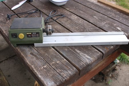
This week, I started making the wooden mast components. Months ago, I bought a small Proxxon lathe for a bargain. However, the lathe is too short to make some mast parts at full length. Additionally, the 10 mm feed diameter limits me in making the lower sections of the bowsprit, mainmast, and foremast, as these are 12.7 mm at their thickest.
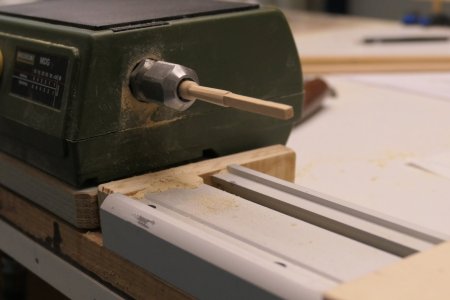
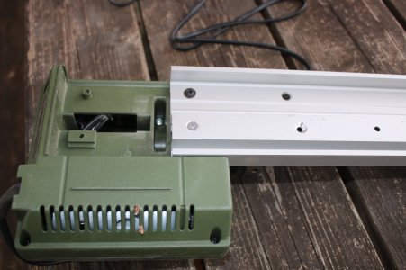
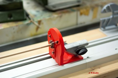
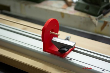
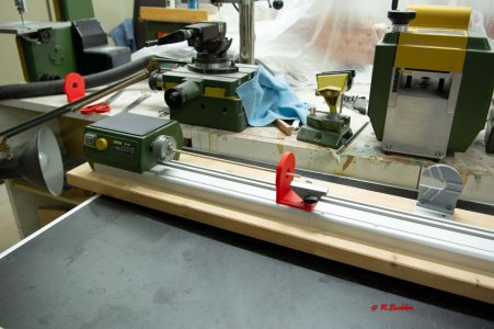
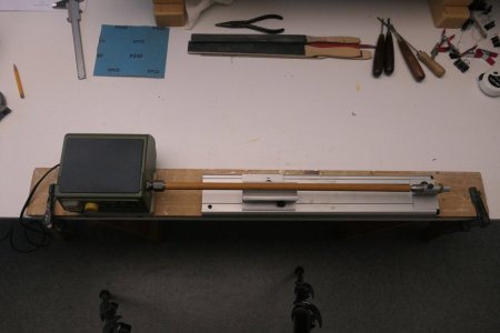
So I disassembled the lathe and mounted the drive and carriage separately on a plank. By moving only the carriage, I can now adapt the machine to any desired length.
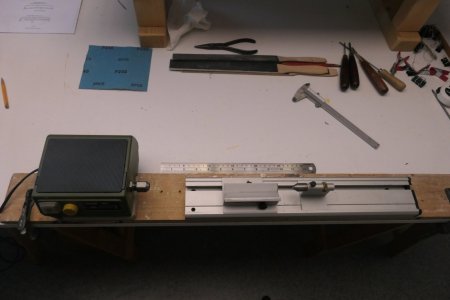
P1034211.JPG

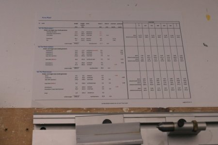
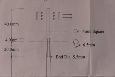
For the masts, I created a kind of production sheet, in which I recorded the modeling and measurements. This makes things easier than working from large drawing sheets.
P1034212.JPG

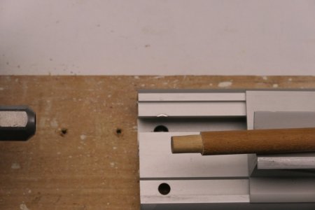
The 12.7 mm dowels from the kit turned out to be slightly warped. Luckily, I still had some old dowels of that size that were straight. After tapering the ends, they were ready to use.
P1034213.JPG

P1034214.JPG

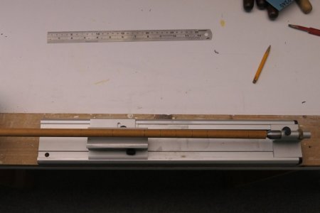
First, all relevant measurements are marked on the dowel, such as transitions from cylindrical to tapered and square. The taper is measured using a standard division.
P1034215.JPG

Next, the wood is tapered with a narrow gouge near the reference marks until nearly the desired thickness. The bottom of this tapered area is darkened with a pencil to remain visible during turning.
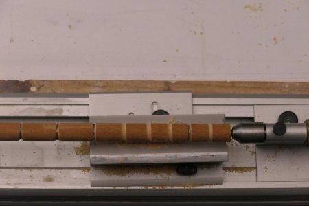
P1034218.JPG

After approaching the black lines with chisels and gouges, sanding blocks are used in grits from 80 to 220.
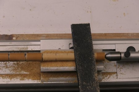
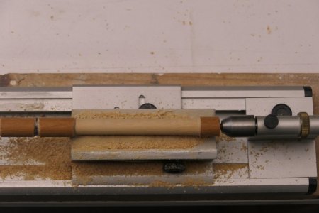
P1034221.JPG

P1034223.JPG

Once the entire dowel is tapered, it’s finished with 240 grit sandpaper. That completes the turning for this mast part.
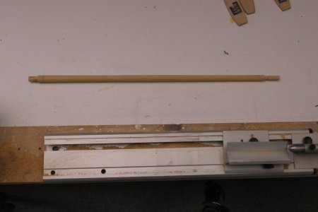
P1034227.JPG

Above, I showed how I tackle the round tapering of masts. But mast parts also include sections that are square or even octagonal. Here's how I addressed that:
P1034239.JPG

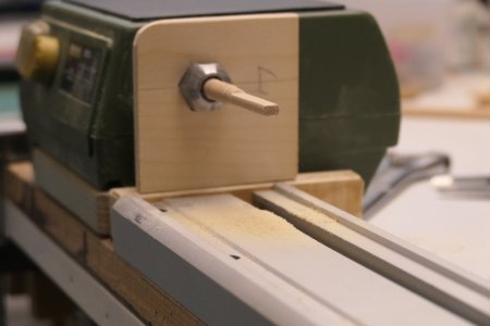
It seemed easiest to perform this while the workpiece is still in the lathe. The key is the position of the nut that drives the chuck. I filed a notch in one corner of the nut, which becomes the reference point to keep track of the rotation.

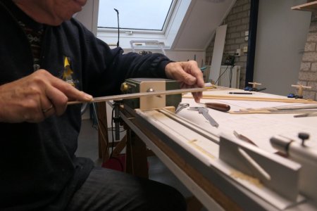
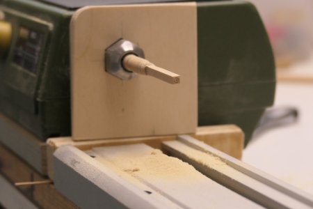
I made a small template that fits the lathe’s nut, allowing me to rotate the workpiece 90 degrees at a time. In each position, a flat side can be sanded onto the workpiece with a sanding board.
P1034228.JPG

P1034229.JPG

P1034232.JPG

Next, the tapered section where the octagon is needed is turned.

P1034233.JPG

To add the octagonal shape, I made a similar template, but with the nut’s hole rotated 45 degrees.

P1034235.JPG

With the final result:

P1034234.JPG

Yesterday, I turned the last parts on the lathe. I really enjoy this work, but the topgallant masts presented some issues. They’re very thin compared to other parts, and unsurprisingly, I had to remake several of them. They keep breaking just before they're done. Grrr…
True turning with a chisel is limited, it’s more filing and sanding while the piece spins. That causes a lot of wobbling with such long, thin rods. A fixed tailstock isn’t a solution either, because the workpiece is often too thin (about 2 mm) to handle sideways forces.
The best option, in my opinion, is to gently support the end by hand so it can flex slightly. And don’t apply too much pressure with tools. You learn that naturally after starting over a few times.

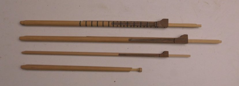
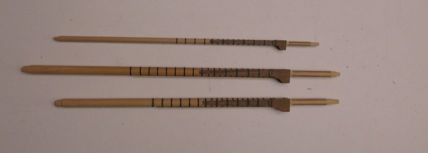
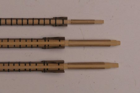
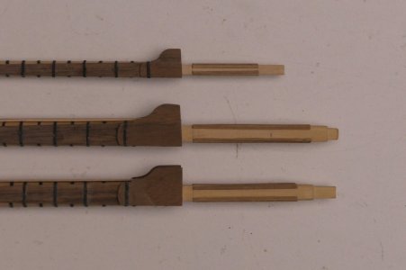
The photos below give a nice overview of the mast parts that are “finished” so far. From top to bottom: foremast, mainmast, and mizzen.

P1034303.JPG

P1034304.JPG

P1034306.JPG
 
30 Making Mast Components

Meanwhile, I’ve started looking into the masts and rigging. There are still quite a few challenges here, like the mizzen topgallant yard, which needs to taper over 49.5 mm from 2.3 mm to 1 mm, with the diameter reduced in proper proportions. I wonder if this will work and stay intact, it’s so thin. But we’ll see.

This week, I started making the wooden mast components. Months ago, I bought a small Proxxon lathe for a bargain. However, the lathe is too short to make some mast parts at full length. Additionally, the 10 mm feed diameter limits me in making the lower sections of the bowsprit, mainmast, and foremast, as these are 12.7 mm at their thickest.
So I disassembled the lathe and mounted the drive and carriage separately on a plank. By moving only the carriage, I can now adapt the machine to any desired length.

View attachment 531083

For the masts, I created a kind of production sheet, in which I recorded the modeling and measurements. This makes things easier than working from large drawing sheets.

View attachment 531084

The 12.7 mm dowels from the kit turned out to be slightly warped. Luckily, I still had some old dowels of that size that were straight. After tapering the ends, they were ready to use.

View attachment 531085

View attachment 531086

First, all relevant measurements are marked on the dowel, such as transitions from cylindrical to tapered and square. The taper is measured using a standard division.

View attachment 531087

Next, the wood is tapered with a narrow gouge near the reference marks until nearly the desired thickness. The bottom of this tapered area is darkened with a pencil to remain visible during turning.

View attachment 531088

After approaching the black lines with chisels and gouges, sanding blocks are used in grits from 80 to 220.

View attachment 531089

View attachment 531090

Once the entire dowel is tapered, it’s finished with 240 grit sandpaper. That completes the turning for this mast part.

View attachment 531091

Above, I showed how I tackle the round tapering of masts. But mast parts also include sections that are square or even octagonal. Here's how I addressed that:

View attachment 531092

It seemed easiest to perform this while the workpiece is still in the lathe. The key is the position of the nut that drives the chuck. I filed a notch in one corner of the nut, which becomes the reference point to keep track of the rotation.

I made a small template that fits the lathe’s nut, allowing me to rotate the workpiece 90 degrees at a time. In each position, a flat side can be sanded onto the workpiece with a sanding board.
View attachment 531093

View attachment 531094

View attachment 531095

Next, the tapered section where the octagon is needed is turned.
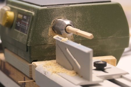
View attachment 531096

To add the octagonal shape, I made a similar template, but with the nut’s hole rotated 45 degrees.
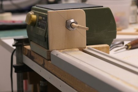
View attachment 531097

With the final result:

View attachment 531098

Yesterday, I turned the last parts on the lathe. I really enjoy this work, but the topgallant masts presented some issues. They’re very thin compared to other parts, and unsurprisingly, I had to remake several of them. They keep breaking just before they're done. Grrr…
True turning with a chisel is limited, it’s more filing and sanding while the piece spins. That causes a lot of wobbling with such long, thin rods. A fixed tailstock isn’t a solution either, because the workpiece is often too thin (about 2 mm) to handle sideways forces.
The best option, in my opinion, is to gently support the end by hand so it can flex slightly. And don’t apply too much pressure with tools. You learn that naturally after starting over a few times.

The photos below give a nice overview of the mast parts that are “finished” so far. From top to bottom: foremast, mainmast, and mizzen.
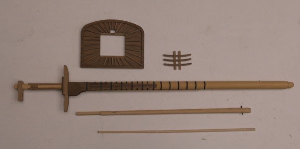
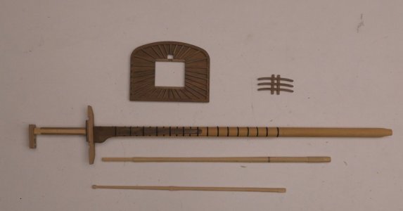
View attachment 531099

View attachment 531100

View attachment 531101
Good evening Wil. This is fantastic. Thanks for the detailed log as well. Cheers Grant
 
Meanwhile, I’ve started looking into the masts and rigging. There are still quite a few challenges here, like the mizzen topgallant yard, which needs to taper over 49.5 mm from 2.3 mm to 1 mm, with the diameter reduced in proper proportions. I wonder if this will work and stay intact, it’s so thin. But we’ll see.
I meant to mention something. Although this may not be of any use since you are making the yards from wood, whereas my medium is mostly 3D printing, I have had great success strengthening yards with carbon fibre rod and bar as thin as 1mm. If you're able to bore a 1mm hole for most of the dowels length, you could insert a CF rod (glue with superphatic glue) and this will make the yard considerably more stiff for turning to shape. It's possible to buy 100mm long drill bits down to 0.5mm diameter, if you search the web for "extra long micro drill bits"
 
31 Assembling the Masts

Over the past few weeks, I was able to continue working on the masts. After the turning and filing of the conical, square, and octagonal parts, the lower masts are now finished, including the bowsprit. Then I could begin assembling the various parts onto these mast sections.
Below is an impression of what is currently on the workbench.

P1034240a.JPG

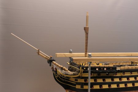
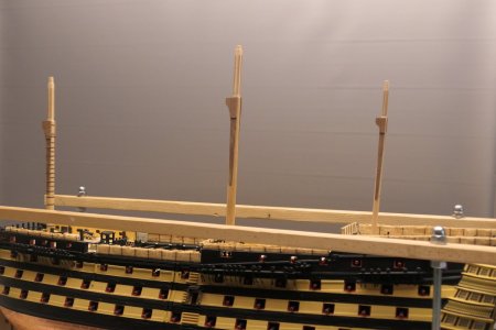
On the ship, it looks like this.

P1034247.JPG

P1034248.JPG

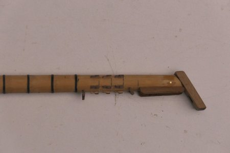
Sharp-eyed viewers will notice that the eccentric bulges for the bowsprit’s seizings are still much too thick. These were not easy to make. I clamped a 12 mm dowel tightly into a hardwood plank, drilled some off-center holes, and then enlarged them to 12.5 mm. What remained were eccentric shell sections that are now on the bowsprit. These will be neatly sanded into shape using the disk sander.

P1034245.JPG

Continuing with the lower masts and the first section of the bowsprit. Structurally, these are mostly complete. What’s still missing are a few eye bolts.

P1034295.JPG

P1034296.JPG

P1034301.JPG

P1034279.JPG

P1034275.JPG

P1034276.JPG

I’ll check everything again before painting this section.
 
32 The Tops

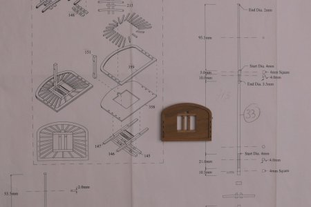
Since I was already working on the masts, I moved on to the tops. Love this part of the process. First, I cut all the pieces, deburred them, and did a dry fit. The drawing looks like this.

P1034250.JPG

P1034252.JPG

P1034254.JPG

To properly place all the beams on the tops, I transferred everything from the drawing to tracing paper and marked the positions on the wood.

P1034256.JPG

After adding all the beams, it looked like this.

P1034281.JPG

Once all protruding parts were removed and the cross trees glued in place, the next picture was taken. Don’t worry, the trestletrees aren’t glued yet.

P1034282.JPG

P1034283.JPG

Once the glue had dried, I couldn’t wait to hang the tops on the masts. I first glued one trestletree to each mast and made sure it faced the correct direction (horizontal toward the keel). Once that glue had dried, I glued the other trestletree, using the position of the top to determine placement and alignment.
This was the result. And yes, the tops can still be removed later.

P1034287.JPG
 
32 The Tops

Since I was already working on the masts, I moved on to the tops. Love this part of the process. First, I cut all the pieces, deburred them, and did a dry fit. The drawing looks like this.

View attachment 534289

View attachment 534291

View attachment 534292

To properly place all the beams on the tops, I transferred everything from the drawing to tracing paper and marked the positions on the wood.

View attachment 534293

After adding all the beams, it looked like this.

View attachment 534295

Once all protruding parts were removed and the cross trees glued in place, the next picture was taken. Don’t worry, the trestletrees aren’t glued yet.

View attachment 534297

View attachment 534298

Once the glue had dried, I couldn’t wait to hang the tops on the masts. I first glued one trestletree to each mast and made sure it faced the correct direction (horizontal toward the keel). Once that glue had dried, I glued the other trestletree, using the position of the top to determine placement and alignment.
This was the result. And yes, the tops can still be removed later.

View attachment 534300
Good morning Wil. Looking very impressive. Your tops are fantastic. Cheers Grant
 
30 Making Mast Components

Meanwhile, I’ve started looking into the masts and rigging. There are still quite a few challenges here, like the mizzen topgallant yard, which needs to taper over 49.5 mm from 2.3 mm to 1 mm, with the diameter reduced in proper proportions. I wonder if this will work and stay intact, it’s so thin. But we’ll see.

This week, I started making the wooden mast components. Months ago, I bought a small Proxxon lathe for a bargain. However, the lathe is too short to make some mast parts at full length. Additionally, the 10 mm feed diameter limits me in making the lower sections of the bowsprit, mainmast, and foremast, as these are 12.7 mm at their thickest.
So I disassembled the lathe and mounted the drive and carriage separately on a plank. By moving only the carriage, I can now adapt the machine to any desired length.

View attachment 531083

For the masts, I created a kind of production sheet, in which I recorded the modeling and measurements. This makes things easier than working from large drawing sheets.

View attachment 531084

The 12.7 mm dowels from the kit turned out to be slightly warped. Luckily, I still had some old dowels of that size that were straight. After tapering the ends, they were ready to use.

View attachment 531085

View attachment 531086

First, all relevant measurements are marked on the dowel, such as transitions from cylindrical to tapered and square. The taper is measured using a standard division.

View attachment 531087

Next, the wood is tapered with a narrow gouge near the reference marks until nearly the desired thickness. The bottom of this tapered area is darkened with a pencil to remain visible during turning.

View attachment 531088

After approaching the black lines with chisels and gouges, sanding blocks are used in grits from 80 to 220.

View attachment 531089

View attachment 531090

Once the entire dowel is tapered, it’s finished with 240 grit sandpaper. That completes the turning for this mast part.

View attachment 531091

Above, I showed how I tackle the round tapering of masts. But mast parts also include sections that are square or even octagonal. Here's how I addressed that:

View attachment 531092

It seemed easiest to perform this while the workpiece is still in the lathe. The key is the position of the nut that drives the chuck. I filed a notch in one corner of the nut, which becomes the reference point to keep track of the rotation.

I made a small template that fits the lathe’s nut, allowing me to rotate the workpiece 90 degrees at a time. In each position, a flat side can be sanded onto the workpiece with a sanding board.

View attachment 531093

View attachment 531094

View attachment 531095

Next, the tapered section where the octagon is needed is turned.

View attachment 531096

To add the octagonal shape, I made a similar template, but with the nut’s hole rotated 45 degrees.

View attachment 531097

With the final result:

View attachment 531098

Yesterday, I turned the last parts on the lathe. I really enjoy this work, but the topgallant masts presented some issues. They’re very thin compared to other parts, and unsurprisingly, I had to remake several of them. They keep breaking just before they're done. Grrr…
True turning with a chisel is limited, it’s more filing and sanding while the piece spins. That causes a lot of wobbling with such long, thin rods. A fixed tailstock isn’t a solution either, because the workpiece is often too thin (about 2 mm) to handle sideways forces.
The best option, in my opinion, is to gently support the end by hand so it can flex slightly. And don’t apply too much pressure with tools. You learn that naturally after starting over a few times.

The photos below give a nice overview of the mast parts that are “finished” so far. From top to bottom: foremast, mainmast, and mizzen.
View attachment 531099

View attachment 531100

View attachment 531101
Hello Wil, your DB250 'mod', gave me inspiration to do something with mine. I unscrewed the headstock, then remounted it using only the first two screws, extending the bed by 80mm. I do have a bigger wood lathe for bigger jobs, so this was a worthwhile mod. Thanks for the idea!

Stuart

IMG_5710.JPG

IMG_5709.JPG
 
33 The Bowsprit

A sharp observer pointed out that I made a mistake with the blocks at the bees on the bowsprit. I appreciated the keen observation. It quickly became clear that I had indeed made a few errors. I think I know why. I found it strange that I had one leftover part, but that happens more often than you'd think.

P1034265.JPG

P1034266.JPG

My solutions:
  • The pulley I installed is useless and will be sealed off.
  • I can thicken the cap on the starboard side to create the attachment for the Flying Jibboom.
  • The semicircular cutout for the Jackstaff is now clearly shown in Longridge's drawing.
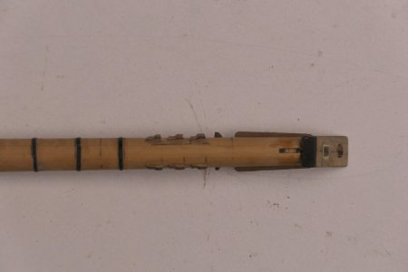
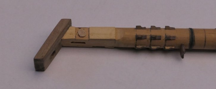
  • As for the bees: the two angled bees must be removed. On top of the bowsprit, against the cap, goes the leftover part. This part is as wide as the bowsprit at that point. I need to recess the pulley wheels into the wood. On port and starboard, the pulleys will be covered with a strip, and on top of that, the two angled bees will return.
  • I also took the opportunity to adjust the saddle for the Spritsail Yard Sling, which didn’t look right either.
I immediately tackled the bowsprit with a small renovation. The photos speak for themselves.

P1034290.JPG

P1034295.JPG

P1034296.JPG

P1034297.JPG

I also made the other mast parts of the bowsprit, from bottom to top:
  • Bowsprit
  • Jibboom
  • Flying jibboom
  • Dolphin striker
  • Jackstaff

Because the Jackstaff is so thin, I made it from a 2 mm brass rod and tapered it.
Now the bowsprit is ready in all its components.

P1034299.JPG

Next up is finishing the various parts and preparing them for assembly and painting Leaving aside the rigging and blocks for now.

 
Good idea, Wil, using a brass rod for the jack staff. Must make a note for when I get there. Incidentally, is it me or has anyone of you fellow 'Caldercraft Victory' builders found the stern 'plume', top decoration to be out of scale - too long? I'm just making the lantern brackets using photos, but on dry fitting I found the deco. interfered with their position, it also appears too long if the relevant positioning in relation to the window is compared.

Stuart
PS. I have just confirmed that the'Trophy of Arms', is too big, so have just ordered a 3D resin printed set of stern decorations from Woody's Model Works.
 
Last edited:
34 Studying

At this point, a lot of information is coming together, and I must say, it's hard to keep everything straight.

My sources include:
  • Caldercraft build instructions
  • Book "Historische Scheepsmodellen" by zu Mondfeld (Dutch)
  • Book "Masten, Blokken & Tuigage" by Orazio Curti (Dutch)
  • Book "Rigging Period Fore and Aft Craft Models" by L. Petersson
  • Book "The 100-Gun Ship Victory" by John McKay
  • Book "The Anatomy of Nelson's Ship" by Longridge
  • Caldercraft drawings (Dutch and English versions) provided by Jan Zwart
That's more than enough material, I think.

Discussions about what more I should or shouldn't use, I'm setting aside for now. There are surely other useful books, but this seems sufficient for now.

Now, a question:

Earlier, I wrote that the eye bolts supplied in the kit are very thin and fragile. They are made of brass and listed as 0.3 mm in the parts list. I used a few of these on the guns. I also purchased larger eye bolts, which I used in various parts of the deck. These larger ones seem way too big in relation to the masts and future yards. On the other hand, the smaller ones seem better in scale but too flimsy for tensioned rigging.
Does anyone have experience with these, possibly with both sizes? What do you recommend?

Meanwhile, I spent a few more hours on the masts. Tidied up some remaining issues and painted everything.
Yesterday, I placed the masts into the hull, and now I finally see how massive this model is going to be.
 
35 The Rigging

Another topic is the rigging. I read somewhere that the diameter of the rope in practice depends on its function. I need to find the source again. Since I'm making my own rope, I must ensure it matches the correct scale.

Caldercraft’s manual assumes a fixed set of rope diameters: 0.1, 0.25, 0.50, 0.75, 1.00, 1.3, 1.8, and 2.5 mm, included in the kit. My gut tells me that in real world the variation is much finer. The steps in the kit are too linear. Since I’m making the rope myself, it’s a great challenge to get this right, I can control the final diameters. From the master builders, I understand that getting the proportions right plays a crucial role in the final result.

So, I spent the last few days digging into the 13 drawings that cover masts and rigging. The woodwork is still manageable, but the rigging and blocks are much trickier. Caldercraft's kit has wonderful materials, but the manual is mediocre. The hull drawings were self-explanatory, but this is different.

The rigging is divided into six phases, each with an overview of required blocks, ropes, etc. The first four phases are easy to follow. But phases 5 and 6 lack the parts lists and these include most of the blocks and rigging. So I need to manually inventory everything from the drawings. But it’s not always clear whether it's a single or double block.

I'm also considering replacing the blocks included in the kit.

Question: Can someone explain how I should approach this phase of the project, ignoring the detailed aspects like knots, seizings, etc.?

I think I’ll have the McKay drawings enlarged. It’s nearly impossible to work from them as they are. The tables, I’ll convert to Excel so I can include proper Dutch terminology and measurements.
Yes, it’s a lot of work, but it will help me better understand everything.

Are all the ropes listed in McKay’s tables meant for a fully rigged ship with sails.
My model will have no sails, so perhaps I can omit some of them. Is that correct?

In other words, this will be a lot of studying, but enjoyable too. It helps me get into it.

The last few months, every spare hour has gone into this. Currently, I’m juggling several subjects, but rope has dominated the past few weeks.

First, I converted McKay’s rigging table for the Victory into Excel. A big job, as it’s handwritten and the PDF isn’t always sharp. A fun study to get immersed in. I’m currently working on translating the various terms.

Alongside choosing to make my own rope, I also delved into the actual rigging used on the Victory. McKay provides a wonderful overview on pages 116 to 119 of all ropes, their sizes, finishes, etc. To be clear, it covers 258 different functions, often doubled for port and starboard or even more (like shrouds). That likely means around 500 ropes in total. A massive task, by the looks of it.

To better showcase the work done on the model, I decided not to show fully deployed sails. That would obscure the view of the masts and rigging. Nor will I include the setup for studding sails. Instead, the sails will be displayed reefed (rolled up). This means the number of rigging functions can be reduced to 168.

Based on McKay’s table and the book by zu Mondfeld, I’ve spent the last few months studying the routing of ropes, how and where they are belayed, what thicknesses are used, and which blocks are needed. Along with some additional drawings, I’ve developed a clear picture of what goes where. Even just naming all the ropes was a massive task, but it has brought me a lot closer to mastering the subject.
 
36 Current Status

Since January 3rd this year, I have taken you all on SOS through 35 summary chapters about my project with the Victory.

In reality, however, I actually started building this magnificent ship back in March 2022. A more detailed report can be found in my Dutch build log: https://www.modelbouwforum.nl/threads/hms-victory-van-caldercraft-door-wil.281364/

Just for the record, up to this point:
• Over the past 3.5 years, I have worked on my shipyard on 385 different days
• So far, I have spent a total of 1,465 hours working on the Victory
• I feel like I’m about halfway there now

Designing and making various tools and aids has been an important addition to the building process for me.

From now on, my posts will be much less frequent and this build log will run in parallel with my Dutch report.

I wish all my followers lots of reading enjoyment in the future.
 
30 Making Mast Components

Meanwhile, I’ve started looking into the masts and rigging. There are still quite a few challenges here, like the mizzen topgallant yard, which needs to taper over 49.5 mm from 2.3 mm to 1 mm, with the diameter reduced in proper proportions. I wonder if this will work and stay intact, it’s so thin. But we’ll see.

This week, I started making the wooden mast components. Months ago, I bought a small Proxxon lathe for a bargain. However, the lathe is too short to make some mast parts at full length. Additionally, the 10 mm feed diameter limits me in making the lower sections of the bowsprit, mainmast, and foremast, as these are 12.7 mm at their thickest.
So I disassembled the lathe and mounted the drive and carriage separately on a plank. By moving only the carriage, I can now adapt the machine to any desired length.

View attachment 531083

For the masts, I created a kind of production sheet, in which I recorded the modeling and measurements. This makes things easier than working from large drawing sheets.

View attachment 531084

The 12.7 mm dowels from the kit turned out to be slightly warped. Luckily, I still had some old dowels of that size that were straight. After tapering the ends, they were ready to use.

View attachment 531085

View attachment 531086

First, all relevant measurements are marked on the dowel, such as transitions from cylindrical to tapered and square. The taper is measured using a standard division.

View attachment 531087

Next, the wood is tapered with a narrow gouge near the reference marks until nearly the desired thickness. The bottom of this tapered area is darkened with a pencil to remain visible during turning.

View attachment 531088

After approaching the black lines with chisels and gouges, sanding blocks are used in grits from 80 to 220.

View attachment 531089

View attachment 531090

Once the entire dowel is tapered, it’s finished with 240 grit sandpaper. That completes the turning for this mast part.

View attachment 531091

Above, I showed how I tackle the round tapering of masts. But mast parts also include sections that are square or even octagonal. Here's how I addressed that:

View attachment 531092

It seemed easiest to perform this while the workpiece is still in the lathe. The key is the position of the nut that drives the chuck. I filed a notch in one corner of the nut, which becomes the reference point to keep track of the rotation.

I made a small template that fits the lathe’s nut, allowing me to rotate the workpiece 90 degrees at a time. In each position, a flat side can be sanded onto the workpiece with a sanding board.

View attachment 531093

View attachment 531094

View attachment 531095

Next, the tapered section where the octagon is needed is turned.

View attachment 531096

To add the octagonal shape, I made a similar template, but with the nut’s hole rotated 45 degrees.

View attachment 531097

With the final result:

View attachment 531098

Yesterday, I turned the last parts on the lathe. I really enjoy this work, but the topgallant masts presented some issues. They’re very thin compared to other parts, and unsurprisingly, I had to remake several of them. They keep breaking just before they're done. Grrr…
True turning with a chisel is limited, it’s more filing and sanding while the piece spins. That causes a lot of wobbling with such long, thin rods. A fixed tailstock isn’t a solution either, because the workpiece is often too thin (about 2 mm) to handle sideways forces.
The best option, in my opinion, is to gently support the end by hand so it can flex slightly. And don’t apply too much pressure with tools. You learn that naturally after starting over a few times.

The photos below give a nice overview of the mast parts that are “finished” so far. From top to bottom: foremast, mainmast, and mizzen.

View attachment 531099

View attachment 531100

View attachment 531101
Hello everyone,

Anyone who has the above-mentioned machine will certainly be annoyed that it is not possible to turn or grind 1:48 scale masts (in my case, Le Requien masts) on it. I gave this some thought and would like to share my solution with you.
First, I ordered the machine bed as a spare part from Proxxon. The part arrived two days later. I screwed the existing machine onto a board and removed the cover cap.


Now I cut a strip of multiplex plywood to 10x10mm and inserted it into the rear opening of the profile. This ensures that the two profiles are joined together so that they are perfectly aligned. I supported this by additionally clamping the tailstock onto the joint.


I then screwed the profile onto the wooden panel and refitted the cover.


This gives me 650 mm of space between the tips. That should be enough for the masts and yards. It worked great on the main mast of Le Requien.


I hope you find this tip useful. I would just like to point out that you should be very careful when sanding. Otherwise, you'll end up with kindling.

Greetings Rüdiger

Hello Everybody,

A small addition to the Proxxon woodturning lathe. I designed a Lynette for the long masts and printed it with a 3D printer. Now everything is a little easier.

ESC9023.jpgESC9024.jpgESC9025.jpg

Greetings
Rüdiger
 
Last edited:
26 The hammocks

In between jobs, I am fiercely studying how to do it all later with all those ropes. To be continued.

Anyway we pick up where we left off. There were still two sloops in half, which still had to be finished. And I had an idea how I was going to make the hammocks, which should be in the nets. Again, my idea started with the application of bandage gauze. After all, the kit says nothing about the nets and the hammocks and then filling things in as you see fit is also a lot of fun.

My intention was to make small rolls of 3 to 4 mm in diameter and approx. 8 mm in length from gauze. The starting point is gauze that is 8 cm wide and not elastic. From this you cut strips about 6 cm long. And you coat these with diluted wood glue, which has been coloured. In my case, I had some left over from the nets. The idea behind it is that the hammocks on the ship will not have been too clean over time and there will be some nuance in this as well.

View attachment 526031

I then took a 1 mm bar of brass and rolled the smeared gauze around it as tightly as possible.

View attachment 526032

Then set this roll aside and carefully pull out the brass bar and let the roll harden. Hard is a big word here, because the highly diluted wood glue keeps the roll somewhat flexible

View attachment 526033

View attachment 526034

After a day, the rolls have hardened and the excess can be cut off with sharp scissors. Then cut the rolls into pieces, I vary a little between 8 and 10 mm, so 9 to 10 hammocks will come out of 1 roll.

View attachment 526035

View attachment 526036

And then it's packing. Depending on the depth of the nets, I put 0, 1 or 2 layers horizontally at the bottom and alternately 2 horizontally and 3 vertically on top. All vertical is also possible, of course. In fact, varying a little will be more realistic.

View attachment 526037

View attachment 526038

I made the hammocks that are in the nets in the photos above yesterday and put them in the nets quite soon after, when they were actually not quite cured yet. No patience of course. The effect, though, is that they are then much more elastic and allow themselves to form nicely. Yesterday at the end of the day, I processed the 19 rolls shown in previous photos. Those were slightly harder this morning, but I think doable. Trimming in both cases went very well with the Japanese kitchen knife, which works like a guillotine and which I also use to trim all my laths etc. Razor-sharp and cuts great.

I currently have 28 rolls of material, good for about 250 hammocks. I estimate enough for half a Victory. For nuance in colour (degree of soiling), I want to apply some darker wood glue here and there at the end, and for fixing I want to apply matt floor varnish. We'll see.

After a few days, all the nets were filled with these hammocks. I did not count them, but estimate that there will be about 500. Although I was dreading it quite a bit beforehand, this part turned out to be much better than I expected. Now that I look at the photos again, they look like huge bales of straw. The sleek look of the hull so far has been somewhat destroyed by this, which is a pity I think. I really have to get used to this "messy" addition. On the other hand, once all the ropework is in place and huge amounts of rope have been put up here and there on the deck, it will not be so bad, I hope.

View attachment 526039

View attachment 526040

View attachment 526041

View attachment 526042

With this, my hull is now almost finished. In fact, only the hatches remain to be fitted. The nets and hammocks are a personal addition, as the kit does not provide these (only the black brackets are

Outstanding job so far!
in the kit). I believe this definitely adds some
 
Back
Top