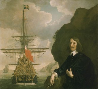
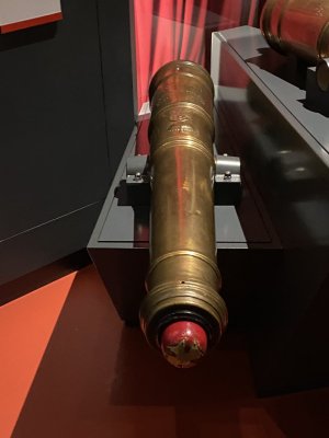
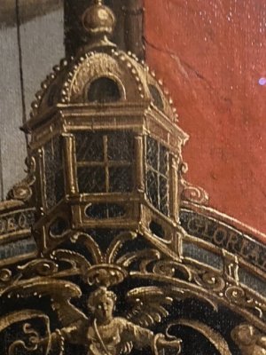
17th Century Ship Design and the Sovereign of the Seas (1637)

Hi Kurt;

Buttock lines are vertical; water lines are parallel to a horizontal, either the keel or the waterline. Each can only be used to plot a series of points on a single plane.

The rising and narrowing lines allow the plotting of a series of points in three-dimensional space, so in a way one could say that they are a combination of buttock and water lines. However, the rising and narrowing lines are created without reference to either waterlines or buttock lines, and are a completely separate entity. As they were normally (not always) segments of curves, the points where each line crossed a frame timber could be calculated mathematically. This enabled accurate plotting at full size, rather than scaling from a draught.

It has been suggested that Matthew Baker was responsible for introducing this system, but the truth of this is unlikely to ever be known.

Ratty
 
Kurt,
To add to Ratty's comment, one can think of the rising and associated narrowing lines on early 17th century ships as tools that were used to draw the bends on the body plan. To be sure, the upper rising line, in conjunction with its associated narrowing line, can be used to give us the actual width of the molded frame at various heights and distances from the midship bend. But this isn't true of the lower rising line or the top timber rising line. Take a look at the top timber rising line on the plans I just posted. Notice that the line is well above the actual frames near the midship bend. Clearly, the top timber narrowing here does not directly give us any information about the actual width of the ship at the top of any frame here. Rather, the amount of narrowing told shipwrights that they were to draw the uppermost part of their frame as if the were drawing it to this point, but they stopped drawing the line when the reached the frame's top. In other words, they drew an "incomplete" line.

This has consequences when trying to interpret early half breadth plans, because the lines don't mean the same thing that waterlines do. Waterlines are drawn at constant heights above the keel and, therefore, give information about the widths of the ship at each of these constant heights. In other words, an individual waterline on a half breadth plan directly tells us how wide the ship is at a specific height above the keel. On the other hand, an individual, older narrowing line tells us about widths at different heights, and we can't directly tell what that height is from the half breadth plan. We have find the line's height from the sheer plan. This is especially true for the rising and narrowing lines of the floor. This makes using these older half breadth plans very cumbersome, and I would have torn what little hair I have left out if I had to use them. Using old half breadth pans is so difficult that I wonder if shipwrights just used them to check their arithmetic; a smooth line showed them they didn't make a mistake, a "bumpy" line showed them they did. So, I don't actually know the extent to which early shipwrights directly used half breadth plans to build a ship. They are of little help in fairing it. I'd appreciate it if someone could shine some light on this for me.
 
Hi Kurt;

Buttock lines are vertical; water lines are parallel to a horizontal, either the keel or the waterline. Each can only be used to plot a series of points on a single plane.

The rising and narrowing lines allow the plotting of a series of points in three-dimensional space, so in a way one could say that they are a combination of buttock and water lines. However, the rising and narrowing lines are created without reference to either waterlines or buttock lines, and are a completely separate entity. As they were normally (not always) segments of curves, the points where each line crossed a frame timber could be calculated mathematically. This enabled accurate plotting at full size, rather than scaling from a draught.

It has been suggested that Matthew Baker was responsible for introducing this system, but the truth of this is unlikely to ever be known.

Ratty
I'm a marine engineer, so am familiar with frame water and buttock lines. But these rising lines are made for a different purpose than scantling, and it's really interesting to learn how shipwrights went about designing a ship using them to construct a hull. My guess is that the rising lines held much more meaning to the timber framers than modelers because of the techniques they used for constructing the framework. We modelers are more concerned with the overall shape of the hull after planking. As such, CharlieT may be correct in describing these lines as tools to check the overall shape of the hull as frames are set in place.

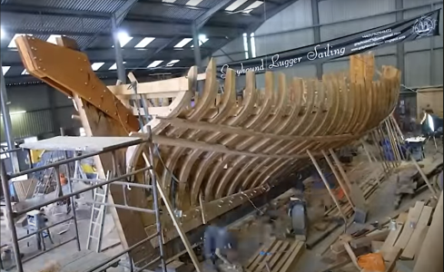
Are the rising lines determined while applying frame supports like those shown in constructing the lugger Greyhound below? Was it a practice to sometimes lay these longitudinal supports along the rising lines for large ships? Or am I confusing two unrelated things here?
1735252224988.png
 
Last edited:
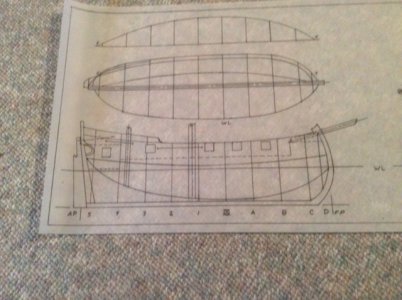
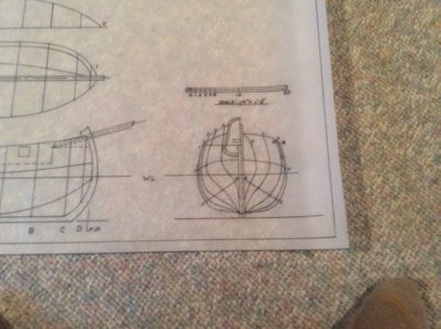
Here’s an example of a vessel reconstructed using formulae from Richard Endsor’s The Shipwright’s Secrets. It is one of the Seventeenth Century British Ketches that accompanied the RN fleet during their great battles with the Dutch. The recurved stem is perhaps exaggerated but there are examples of this type of stem during their great battles period. See the very early Eighteenth Century Hoy Lion. If I ever get around to building the model I will reduce the curvature of the ste.

I don’t remember the exact procedure but I began by using available published dimensions; length, beam, depth, etc. I also made wooden moulds for the midship bend using Endsor’s formulae. I then drew the profile and added the height of breadth line, a circular arc. The body plan sections were formed from the moulds. The diagonal is a modern day fairness check.

IMG_1158.jpegIMG_1162.jpeg
 
Hi Kurt;

Rising and narrowing lines were drawn through a series of known datum points at the stern, midships and bow.

Rising lines show on the sheer plan, and narrowing lines on the half-breadth. Each line is visible in both views, as the curvature is three-dimensional. In other words, the rising line of breadth shown on the sheer plan, becomes the narrowing line of breadth on the half-breadth plan. They were used in conjunction with the 'whole moulding' method in a process which I am still endeavouring to understand myself, and so cannot explain fully.

There were various rules applied to the drawing of the curves required; most of the time the forward half of a line was drawn using different rules to the after part of the line. The degree of curvature could be varied within a range, using a set of proportional rules. Altering the curvature affected the ship's performance in different ways, and was seemingly well understood at the time. There are several treatises on ship design written in the early years of the 17th century, which lay down, more or less, the proportional ranges for the curvatures, and the reasons for making the choice. The clearest in this respect are the Newton MS, and the Scott MS. The Newton MS appears to be taken in some part from the Scott MS, which is undoubtedly the earlier of the two (its author died around 30 years before Newton was born) However, the Newton MS is a lot easier to read; the Scott MS is only readable by someone experienced in the handwriting and vocabulary of the time.

The Salisbury Treatise, which is in many ways more detailed than either of the previous two, as well as more wide-ranging in its coverage, is a very useful guide to draughting a ship, and is well-analysed in Peter Kirsch's book 'Galleon', which I recommend if you do not have a copy in your library. The copy of the treatise on which this is based exists in the National Archives at Kew, and was named after the person who first brought it to public attention in the 1950s. This is normally believed to have been written around the 1620s.

This version, which is the only publicised version, was the only one known until quite recently, when a second copy came to light, which includes several paragraphs missing from the Salisbury version. Neither of these versions is the original though, and neither has the tables attached which once accompanied the treatise; we know these existed, as they are referred to at the end of the MS.

As Roger mentions above, Richard Endsor's book 'The Shipwright's Secret' is a very helpful guide to the methods used to create the draught for a ship, and is also well worth getting if you can. This is based on a document from later in the 17th century written by Jonas Shish, a Master Shipwright; although the method of use is the same, based on rising and narrowing lines.

Taras Pevny has written an informative thesis on the subject of draughting using these lines, called 'Capturing the Curve'. The first part of this discusses a previous hypothesis put forward by a different writer, but once past this stage, the explanations are clear, and are illustrated by a series of 3D computerised images, showing all the lines used.


Ratty
 
Last edited:
Hi Kurt,

Please see my blog on the sots explaining/visualising how these were used in the construction of every frame position.

 
Endsor’s book gets vague relative to the lines at the bow. In the Texas A&M book analyzing the archeology of the LaBelle wreck there is a chapter titled Capturing the Curve. The same? I believe that the lines for my ketch are believable except for those at the bow. Correcting them is a matter of juggling the radius of the stem and tumble home of the hull.

At my age, time flies by and I am reluctant to engage in building another model until I complete the current one, but I certainly would like to try my hand at my little ketch.

Roger
 
Hi Roger;

The LaBelle wreck chapter is written, I believe, by the same person; Taras Pevny. Not having yet read the report, I cannot say if the chapter is the same, or if the version I have seen is an expanded one, with more detail.

Ratty
 
Back
Top