74 Gun Vasseau by Jean Boudriot from Ancre'

This Morning doing a little drawing before Santa Festivities.

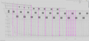
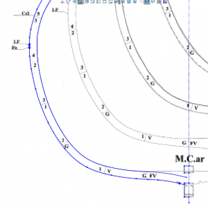
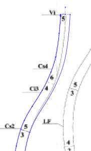
Working on the Dead Flat Frame and this will show really nicely how the French did the frames on their 74 guns.

So for the most part there is no taper of the futtocks they are all the same width from floor up to the top timber.
Once you hit the top timber you get a taper to half the width of the frame. This makes life a lot easier. I will later have to read in depth where they get their thickness dimensions from, but this makes life a lot easier doing french ships than British when trying to taper the futtocks all the way up.
74 Gun -64.png

74 Gun -65.png
 
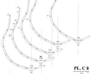
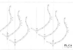
So the hard part of reading these drawings are the way they are labelled. he uses weird numbering system for all the parts and you have different parts in opposit areas of the ship labelled the same.

For example his frames in the bow are labelled as C1, C2, C3, C4 etc and his aft frames are labelled C1, C2, C3, C4 etc

I am ASSuming that the way they are drawn with some drawn on the right side of center and some on the left they are as is in body plan where left is aft and right is fwd.

I have an email sent to Mr Gaetan Bordeleau asking for verification on this.

I am posting a couple images so you can see what I mean

74 Gun -67.png

74 Gun -68.png
 
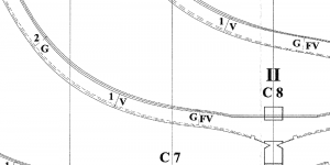
Another thing is the multiple lines drawn on each frame. It took me a couple mins to figure them out but he has drawn both the Fwd and Aft staions together to make the frame. so you need to really read to understand all the lines.

The good thing is he follows good drafting standards when showing his dashed lines which makes plans easier to read. I have seen some plans where people have dashed lines that should be solid lines which makes it hard to figure out what they are doing.


74 Gun -69.png
 
So the hard part of reading these drawings are the way they are labelled. he uses weird numbering system for all the parts and you have different parts in opposit areas of the ship labelled the same.

For example his frames in the bow are labelled as C1, C2, C3, C4 etc and his aft frames are labelled C1, C2, C3, C4 etc

I am ASSuming that the way they are drawn with some drawn on the right side of center and some on the left they are as is in body plan where left is aft and right is fwd.

I have an email sent to Mr Gaetan Bordeleau asking for verification on this.

I am posting a couple images so you can see what I mean

View attachment 69290

View attachment 69291

Hi Joe,
The drawings look very good, you could renumber the frames on your model to make things more organized and easier to work with.
Mike
 
well the plan sheets label them 1-30 then the parts sheets label them C1-whatever for front and back. why he didnt just label the frames as they are on the sheet is beyond me.

But when I am fully finished will have a very accurate detailed set of french 74 gun plans ))

Merry Xmas everyone and Happy New Year. heading to my sons in a few to beat up on my grandkids for a while
 
So tonight got the mid frames and aft frames drawn. Now I just have to fare them in. Lofting is going to be tricky the way they all land on the keel but we shall see if I can figure that out. I can tell they are out of fare, but shouldn't be too bad just enough to cause a lot of sanding i don't want to have to do.

Also I need to do the loft in order to get the in between frames without going back and tracing every frame then trying to fare everything. This way if I do the main stations they used to loft the hull and get the intermediates I can do similar but with 3D making mine more accurate, that is if I can get it lofted. It is all the way the frames hit the keel. In the middle they go down the side to the rabbet, in the aft the whole side is the rabbet.

74 Gun -70.png
 
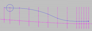
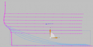
I wont show all but maybe 2 or 3 of the real bad ones I may find but this image will show what I am looking for. As you can see the first waterline looks pretty decent except a small dip at the next to last station so I will clean that up and later redraw that frame.

74 Gun -71.png
 
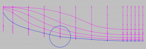
Well first 4 Waterlines done and other than the first one I havent had to touch any, However the errors I saw were more towards the top of the frames so we will have to wait and see

74 Gun -72.png
 
Well found that the 2nd and 3rd waterlines from the top were off so adjusted most of the frames, and have 3 more to go after work tomorrow then fix the waterlines and everything should be good. Then I need to do the insides of the frames and can then loft and get all my starions I need to work out the aft lofts I hope.

So far I ave abt 8 total hours or so in the loft which isn't too bad. Another thing I had to do was to bring all the dead flats up to the heights of the other frames to make the loft work properly then I will just cut the loft where I need to for the step downs on the frames.


74 Gun -74.png
 
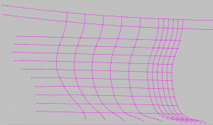
I was a bad boy today called in sick lol but i never call in so they will believe me )). So I got my frames all fixed (Front Dead Flat to Aft Frame) and the body plan is looking good. Next I will adjust my waterlines and the outside of the frames and the waterlines will all be fare.

Then I will start the Inner part of the frames to fare them up.

74 Gun -75.png
 
So I thought I would explain a little something here before we continue. I like to do cad work first so I can correct errors and there have been some errors pointed out with the plans. Yes they can be used to build from but will require a bit of sanding. I am not trying to do a cad tutorial here but going through my process from beginning to end ie from cad stage through building. the reason for this is I can just start building, but then someone else spends the big bucks out and then wonders why mine is so different from theirs and why I am having less problems.

This also shows the nice complete process that I use for every project not just ships but my R/C Models too.

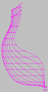
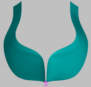
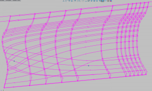
So I just did a surface loft for shits and giggles and it came out pretty nice. Some of the funny looking shadow you see are just because of the hull shape and because I didnt take the time to add more spotlights etc I just went with the default. I will however later once I get the forward half done add some Buttock Lines just to give me that third dimension of fareness, but so far looks good and have 2 dimensions of fareness.

The Last Image shows my waterlines and stations lit up for reference.

74 Gun -76.png

74 Gun -77.png

74 Gun -78.png

74 Gun -79.png
 
So tonight after work if not too tired have a little fixing to do. Last night added 4 buttock lines and found small hiccup with a couple aft frames. When I fix one part it creates another to fix. They were really off on like 3 aft frames for the inside but that got fixed now it's the aft to fix and ready to go
 
I finished the Buttock fareing tonight and there were 2 really messed up frames. well not that terribly messed up but enough it would take a lot of fidgeting so I will just Loft the Hull without those 2 and all my guides will give me a nice fared hull and I can extract those 2 frames from that.

74 Gun -81.png
 
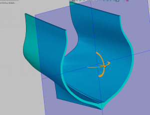
I tilted this one at an angle so you can see all the lines involved for the lofting process to get a fare frame. it is similar to what you do in 2D but here we can see it in 3D and how it affects each line as we move it real time. Also the 2 Blue dots are the frames I took out that were corrupt.

74 Gun -82.png
 
Hello Joseph,
I for one am not very computer savvy. I am the type of builder who jumps in and, "Sink or swim" will figure things out as they come along. That being said, I am quite impressed with other people's ability to use this concept of drafting lines via a computer. Out of curiosity, how long of a process is it to draw these images on a computer? I'd imagine that it take a lot of man-hours to complete even before getting into the actual build itself. Many thanks in advance, Raymond.
 
well rough guess I have maybe 20 hrs total working time on what I have so far. its really not long yet the tedious time comes making all the part files afterwards. I get a lot of distractions with dog wanting out every couple hours, work and worst is wife aggro. when shes at work and during day when dog sleeping most the day I can buzz through but I also have abt 30+ yrs of drafting and cad experience.

Just to give an example, for a british 74 gun just to make all the frames I have about 800 ish part files. It take 9 parts to make one half of a double frame so 18 per frame if I am using chocks on the frames. 5 if I go the cheap way without the chocks.

then you have the keel, transom, head and that's just for the outside of the ship.
and if I want to do planking properly so you can remove certain planks then how many hundreds of hull planks and deck planks are there.
so basically 1 part file for every part you have to make I need to do the same in the computer.

I enjoy it though it is relaxing if not frustrating at times.the hardest part is the hull loft after that its easy just tedious and time consuming, but it makes for an awesome set of plans and an interactive file. when I get these aft frames lofted I will make an e-drawing file for people to look at and see in 3D. Just need to download the viewer which you can get here so you might want to get the viewer now https://www.solidworks.com/sw/support/eDrawings/e2_register.htm
Just need to check the dot that says viewer only.
 
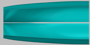
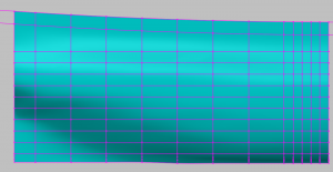
So it wouldn't let me use the Buttock lines it said something about not in the right order and I tried several ways. its all fine until it hits the aft where it dips up and in. so I will redo the loft a couple different ways like take out some waterlines and add the buttock. if nothing else I will create some more stations in the aft from the loft and clean them up. it is all trial and error and it doesnt help that in the couple hours after work before bed i am rushing it. I can always do it sunday on day off if I have to.

but this cross sections looking good so far
74 Gun -83.png
 
Back
Top