Cad design Alfred stern cad designing

Dave am not sure were the roof over the balcony came in to play and I thought we was talking about the balcony itself.

yes we were talking about the floor of the balcony itself I just mentioned the roof because it too has to extend out.
 
Gary and I have been talking via phone and he is putting a lot of effort into the research and design of this stern project. We both have extensive personal libraries collected over many years in the hobby. We agreed neither one of us plan on writing and selling books, drawings or doing this for profit. So we are going to do something never before done on any other forum and it might make the pirates jump for joy. WE are going to give it all away as a forum project by up loading the working CAD files. Anyone can join in to create 3D drawings of the parts, laser cut stuff from the files etc.

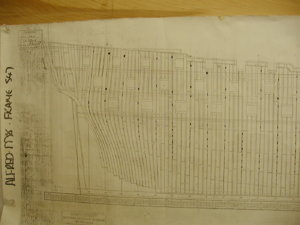
One reason is this, take a look down in the lower left corner notice the copyright. You can not use museum plans for any commercial use without a license you can not even change them or redraw them ALL rights are reserves when it comes to museum plans.

All the work so far is based on drawings by Harold Hahn with a few tweaks here and there that i made so what will end up with is a hybrid between the museums plans used as research and Hahn's plans which does have museum permission gotten many years ago.
Now a warning to pirates this is not a free ticket to make anything you would sell we know where it all came from and you might find yourself in more trouble than what it is worth. However as the project develops there are provisions available to create things like carving sets, laser cut parts etc. That can be discussed at a later time.


P8300109.JPG
 
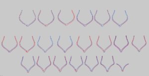
first in a series of CAD drawings here are the frames
they have not been broken down as cutting files that will come along later as each frame is broken down into its components for either laser cutting or to place on sheet stock to be hand cut.
this is a screen shot of the CAD file uploaded is the cad DWG. file

cad1 frames.JPG
 
Last edited:
sorry Dave the roof over the balcony doesn't extend out and doesn't go any further then the side counter timbers see post 121. What sticks out past the side counter timber is the taffarel, which attaches to the poop deck deck transom and holds most of the carving. The roof over the balcony is really the bottom of the poop deck above. Gary

oh! ok your right it is not a roof over the balcony i see what you are talking about.
sometimes stupid just happens I know better thanks for that slap WAKE UP!
 
Last edited:
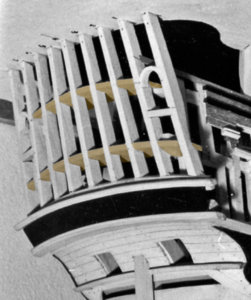
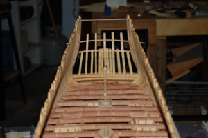
found an image before the balcony rail was installed. It appears like Harold simplified it by just adding one solid sheet for the balcony floor and my guess he glued the rail to the edge. Behind those pillars would be the stern timbers cut off at the floor height and filler blocks added between the timbers.
As for how it really was done is still a guess which I think it was the deck planking run out to the edge of the molding, but if that was done there still had to be something that tied all the ends of the planks together. I doubt that molded edge was cut into the ends of the deck planks.

img689.jpg
 
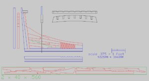
here is the CAD drawing for the keel, stern post and deadwood. What you have here is the assembled deadwood then a break down of the parts.
parts are
wing transom end, side and top view
stern post side and profile views
inner post side and profile view
keelson
keel
false keel

cross section view of the deadwood
at the bottom is a break down of the deadwood

files are a CAD DWG file and a DXF file that can be imported in several programs.

deadwood.JPG
 
Excellent work Dave. I just reviewed your dwg file and all of your vectors are pretty much laser-ready other than scaling and grouping. Much better than what I usually see, you even have the vector line thickness set down to hairline which eliminates a bunch of extra work on the maker side. I would suggest giving yourself a little more space between the grouping of your parts. While it is true that we want to save wood when mass producing kits, it is better to space the parts out to get better quality cuts for a single model or low-run custom kits.

This is a great log!! You have put a lot of work into it!!
 
the reason they are spaced close together is to fit them on 2 inch wide sheets. The narrower the sheets the less the sheets will cup and warp. The part layouts will not work for cutting them with a scroll saw, the parts are way to close to each other. I can create the parts as objects that way they can be moved around without falling apart.

coming up next will be the files for the stern timbers and upper transoms

in the works are the windows and carvings


This is a great log!! You have put a lot of work into it!!

thanks but lets not forget the research work Gary Bishop is putting into this project. I may be sitting here doing the CAD work but Gary's model building and ship construction knowledge is extremely valuable to the success of this.

I hope some of the forum members will use the CAD files and create some 3D STL files.

i do have a 3D artist who does fantastic sculpting on stand by waiting for my files. Once these files are done and STL files created then they can be used for CNC carving or 3D printing.

once again like a group build this is a SOS forum membership project that deals with design, CAD drawing and 3D modeling. In time it will evolve into CNC and laser machine work and 3D printing.
 
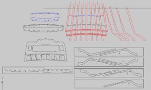
this is the file for the stern timbers

notice on timbers 1 , 2 and 3 there is a cut in the profile of the timbers leaving only a thin area. This is because those timbers are cut away at that location. I left the top joined to the botton until the two upper transom pieces are fit.
The top view of the transoms show the notches for the timbers and the side view shows the arc. These pieces present a problem for laser cutting, the top view is no problem but the profile arch requires stock to be 1 3/8 thick to cut that arch.
The stern itself can be cut from thin plywood or solid sheet stock.

stern timbers.JPG
 
Last edited:
the profile arch requires stock to be 1 3/8 thick to cut that arch

You lost me a little bit on that statement? Are you saying the stock for timber parts 1, 2, 3, and 4 need to be 1 3/8" thick? If so, not biggie. Either just CNC them or laser them in 2 halves and glue together.
 
You lost me a little bit on that statement? Are you saying the stock for timber parts 1, 2, 3, and 4 need to be 1 3/8" thick? If so, not biggie. Either just CNC them or laser them in 2 halves and glue together.

the stock for the stern timbers is 3/8 thick that is for parts 1, 2 , 3 and 4

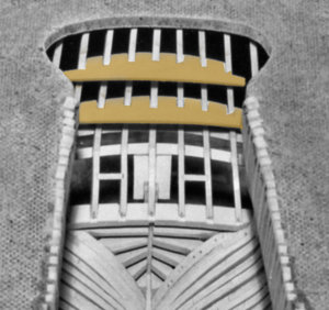
in the drawing to the left of the red stern drawing are the transom pieces and here they are in place. In the first picture you can see they arch. when you go back and look at the drawing the side view shows the arch. In order to cut that arch in the lower (black) drawing of the transom you need stock at least 1 3/8 thick

trans1.jpg

trans2.jpg
 
Dave what about putting a joint in the stern timbers right at the quarter deck transom because they have to be cut off there any way and it would save on the width of the timber. Gary

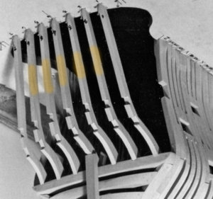
what Harold did was built the stern with the timbers as one piece then after he added the transoms and stern then he cut away the yellow section of the timbers. What i did was draw the sections that are remover smaller which would locate exactly where the two transom pieces will go

tim1.jpgtim2.jpg
 
In order to cut that arch in the lower (black) drawing of the transom you need stock at least 1 3/8 thick

I see what you are saying now Dave. Curious, how thick are the transom parts? Can't the arch be shaped over a former from a flat piece? If not, I would just fab the transom part by CNC if this were for a kit. Other option would be to laser the notches on thinner wood, glue them together, and then use a former. Heck, multiple solutions... LOL.. easy stuff.
 
ok lets hear from Gary and see what he did

at 3/8 scale the lower transom piece is .200 thick a fat 3/16 x 1.250 wide at the center and 11.637 long now can that be bent?
 
Last edited:
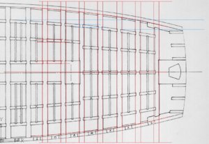
the lower deck construction

here is what Harold drew in his plans so what I am going to do is use his drawing of the deck and add knees.

deck1.JPG

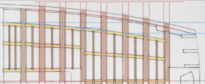
the layout in CAD I only need to do 1/2 the deck then mirror the other side. The blue lines run at a 90 degree to the beams, the carlings follow an arc so each carling is at an angle to the beams except for the center ones. The ends of the carlings notch into the beams.

deck2.JPG
 
Intrigued, confused, and impressed. Just shows the diversity in our hobby. Not at all how I would approach this but that is because I am spoiled with CAD, CNC, and Lasers. All I can say is wow!!!

I know what you mean my approach is first CAD design the 3D modeling, machine work.
 
Back
Top