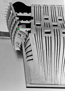
Cad design Alfred stern cad designing

I deleted the posts on the deck because I drew the deck in the wrong location
decks05.jpg

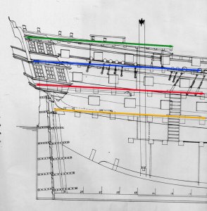
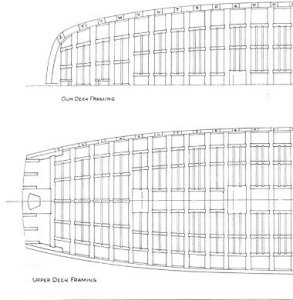
here are the decks at the top the green line is the poop deck
decks04.JPG

the blue line is the quarter deck

decks03.JPG

the red and yellow lines are the upper deck (red) and the gun deck (yellow)
decks02.JPG

I switched these two decks so I have to redo them.
 
Harold did not put any deck knees in his drawing or on the model. I added knees to the lower and gun deck but noticed the quarter and poop decks are lighter built with smaller size deck beams. This brings up the question were lodging and hanging knees used in these lighter built decks?
 
how about the use of carlings and ledges on the quarter and poop decks?

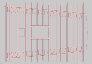
here are the lower deck and gun deck I need to draw the hanging knees then break down the decks into their parts

lower deck1a.JPG

gun decka1.JPG
 
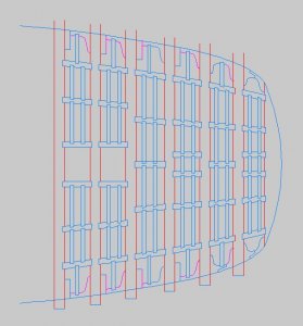
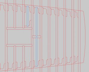
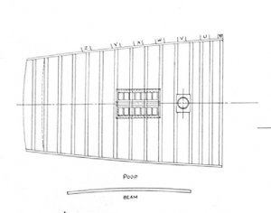
here is the poop deck with just the beams, hanging and lodging knees and carlings for the sky light.
these decks with all the knees is taking a lot of time.
on all these decks i am leaving the beams run over the edges because when it comes time to laser cut the beams i wanted to leave extra length so they can be fit to the hull. That square is for the mast partners.


poop deck1.JPG
 
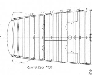
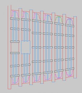
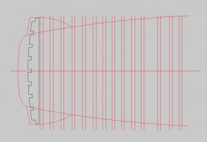
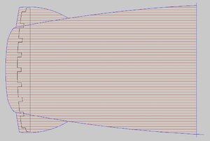
alright I started on the quarter deck this deck has a lot going on so here is the basic "floor plan" with the beams and transom ( the black piece) in place.
i did notice the lower deck and the gun deck have 6 and 7 main deck beams and the quarter deck has twice the amount.

quarter deck1.JPG
 
the plans Harold drew look a lot like the museum plans. Now my question is about carlings and ledges on the quarter deck. with twice the amount of beams it would seam there is no need for ledges between the deck beams. for sure there would have been lodging knees. I am thinking maybe 1 ledge between beams.
 
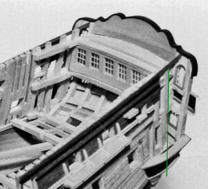
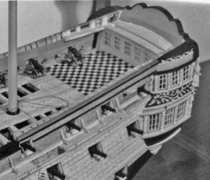
just sitting here thinking about the layout of the quarter deck. The trick with drawing is taking points from a 2d drawing and placing them in another view. Here is the basic layout including the quarter gallery and balcony. The black shape is the transom and the blue lines are the inside of the hull.

qgal5.JPG


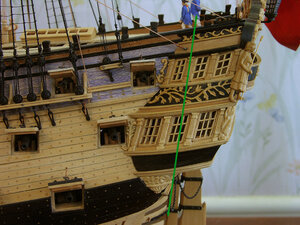
drawing a line from the inside of the stern post it looks like most of the gallery is beyond the side of the hull

qgal6.jpg


The same green line is drawn at the last hull timber and it does align with the top image. Beyond the green line where the windows are is part of the stern timber construction.

qgal7.jpg

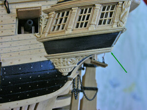
below the gallery is the arc of the stern timber which ends at the green arrow. This all comes down to is where does the side of the hull end and the stern construction start. Well no doubt the hull ends at frame Z so technically speaking everything past frame Z is stern construction. Seems to me most of the gallery is part of the stern construction and really not sitting against the side of the hull.

qgal8.jpg
 
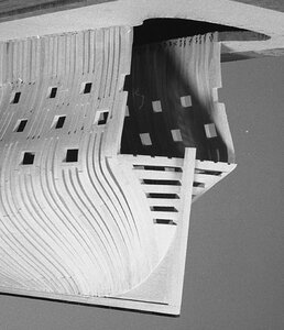
this is where the hull actually ends beyond this is all stern construction.

qgal9.jpg

here is that little green dot so really the quarter gallery is part of the stern construction.

qgal10.jpg

ever hear of the old saying "get your ducks in line" same applies to designing and drawing get all you points in line
 
scratch building vs scratch building

and what is the difference?

scratch building from an existing set of plans drawn by someone else you as the builder need to look at those plans and visualize the structure in 3D
scratch building from drawing your own plans you as the draftsman need to be able to take any point of reference from any 2D view and project it into another view.

This is where 3D modeling come in handy
but you have to see the model in 3D in your head in order to do the basic CAD drawings to created the 3D model.
 
seems like there is little action from a forum point of view, let me assure you there are many hours spent in front of the computer drawing.

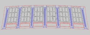
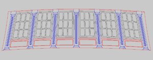
here is the back wall of the cabin, first of all the exact height and length had to be established so it would fit between the frames and between the quarter deck and under the poop deck. Once that is established then comes the details. There are no 90 degree lines everything is drawn to fit the shape of the wall.

cabin wall1.JPG

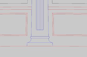
zooming in, the details begin to show like the flutes in the pillars and the corners of the panneling

cabin wall2.JPG

this drawing is still not done because I have to draw a sectional to establish the depth of the panels, thickness of the pillars and window frames etc. The sectional drawings will aid in the building of the 3D model.
As, I do these drawings, I come to realize everything fits exact, in other words the length and width of the back cabin wall is based on the CAD drawings and the CAD drawings are not the same as Hahn's original drawings there could be as much as .070 difference, this will add up as more of the drawings are done.
 
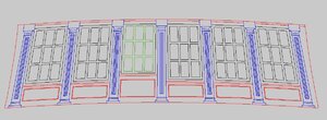
I found the error in measuring so I fixed one window the green one

new window.JPG

this is the back wall there are no doors in the back wall but there are 2 doors on either side but that is in the side walls I have not drawn them yet
 
when I was drawing the wall those windows did look a little long but I did it anyhow so guess what I will be doing tonight?
 
and here is the back wall between the cabin and balcony 2.0 with shorter windows

back wall2.0.JPG

below is the old drawing you can see the difference in the size of the windows

cabin wall1.JPG

on the original Alfred drawings in post #168 and post #175 it clearly shows doors going to the upper section of the gallery and leading to the balcony off to the side and not in the back wall.
Yes it is possible some ships did have doors in the back wall but not the Alfred.

Beside, this just made it easier for the upper's to go out to the stern walk and not have to go through the bathroom were the toilet was.

i do not think the toilet was in the upper section of the gallery it would have been in the lower section the upper section was a short hallway with a pocket door to the balcony.
 
Back
Top