Cad design Alfred stern cad designing

looking through the book Navy Board Ship Models by John Franklin
it looks like painted frieze work was common and for the most part was scrolls the other was like Hahn did and just painted a solid color.

like Gary said you really can not go wrong because there is nothing to go by
can you post an image of what was on the Warrior?
 
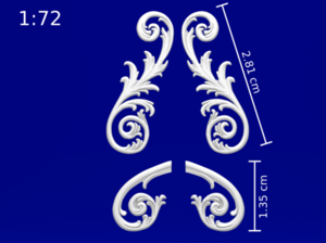
I think I will get some 3D printed resin scrollwork down the sides of Alfred. It may not be perfectly accurate, but I think the model needs some sort of decoration.
This is from Victory in 1/72 scale. I reckon a continuous scrolling pattern along the sides would be cool .

..710x528_24115649_13265959_1531580706.png
 
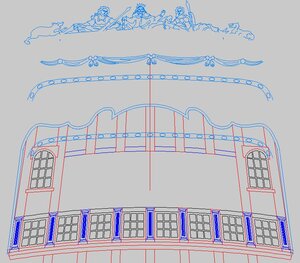
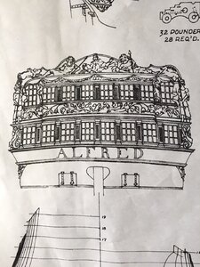
once the shape of the stern was established by the stern timbering it comes time to add the moldings and carvings. All these have to fit on the stern. Starting at the very top the molding was drawn. The cad drawings will be converted into 3D models as STL files. But what i am doing now is to establish the shape, size and location on the stern.

stern carvings.JPG

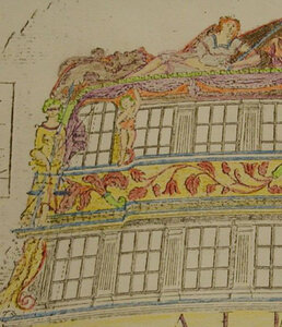
some parts are open for artistic interpretation like the small figure on the left between the windows

boop.JPG


looks to me like Betty Boop

betty boop.jpg
 
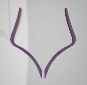
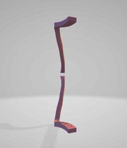
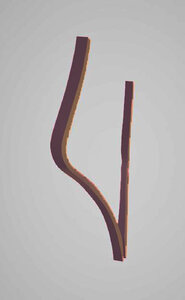
the artists doing the 3D sculptures will have to know thickness, shape, and size of all the moldings and carvings and that is where I have to establish all the parameters for them to work in. So I need to also provide cross sections of moldings etc.

this is a long tedious job to create a 3d model with CNC, STL and laser cutting files just to give you an idea here is the CAD file time

81 days 17:59 hours 22 minutes . 029 seconds that is how long this working file is live on my work station
I do not shut down the system I hit sleep. I tend to work on the file in bits and pieces between everything else.

the time is just my time and it does not include the rest of the designers and artists working on the 3D model. This I hope answers questions like Donn Farr has like why don't companies or people just crank out 3d models as instructions. Imagine a company having to pay a team of CAD designers and 3d artists to do something like this.
people around the world are working on this project with me and they are professionals so it is not like someone at home wasting time trying to figure it out as they go. They know the programs and how to do the job
 
Last edited:
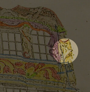
when you look at the drapes in purple in post #236 they cover part of the last window, this makes me wonder if the original draftsman just drew it that way but the builders thought hum that ain't right and changed it.
 
I concur with Dave here. CAD, 3D artwork, and model design takes a huge amount of computer time. Even to copy someone else's work is a huge effort. To do from scratch even more work. To take a piece of art from one laser to another laser is work. To carve a 3D sculpture on one CNC to another CNC machine is extra work. Everything in this space is "custom". There is no WYSIWYG (what you see is what you get).

I hope our friends understand and appreciate this is a skill-space all on its own.
 
I read someplace the art movement in Europe would evolve into different phases, during the Alfred's time it was Egyptian and Egyptian symbols were showing up in art work. owning objects from Egypt was all the rage in jolly old England.

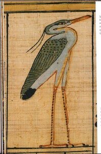
I recall seeing that bird in Egypt carvings there is a name for that bird. I need to look again.
 
All the Hahn plan sets lacking of details

Hahn simplified his models so the first time scratch builder would be able to build the ship. This was one of the things the critic's of his work pointed out. Hahn said over and over in letters, articles and in talks he gave his models were the basic construction and any serious build should fill in the blanks with their own research.
 
Let me ask this. If you was telling a story of Alfred the king where would the birds fit in to the story or are they just a carving. what made these birds specal when it came to king Alfred him self. The bird in the middle of the stern railing is I believe a raven which was a symbol on King Alfreds flag when he was a war with the vikings. If it blew in the right direction the would have a good day and win the battle. At least that when I have pull out of his book. Gary

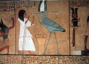
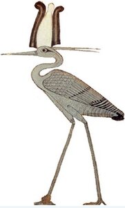
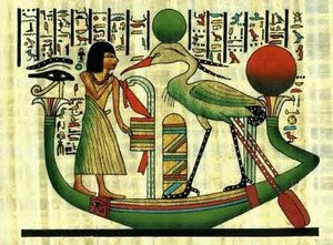
your most likely correct the bird at the top would be a raven. The two birds on both sides of the lower windows are Benu birds.
How they fit into King Alfred? I think carvings on ships were not just random decorations they had deep mythological meaning. There were back stories to the figures and symbols used in the carvings.

the sun never sets on the British empire, Benu is a bird of the sun and will always regenerate


The Benu Bird is linked to that of the phoenix. Both are birds of the sun, both are self created, rather than being born from other creatures, both undergo death and become symbols of regeneration. The Egyptian sunbird is identified with Re, the Sun God. The word Benu in Egyptian means both purple heron and palm tree. The Benu was identified with the Temple of the Sun God at Heliopolis, which was revered by the Egyptians as the sacred mound from whence the Sun god, in his aspect of the Benu Bird, arose cyclically to renew Egypt; another feature which was shared by both the phoenix and the Benu Bird.

The Greeks knew the Egyptian Benu Bird as the Phoenix. A legendary bird without parents and offspring it nurtured itself on sunlight and sea spray. Brilliant in appearance, its feathers were gold, red and white; its eyes were green as the sea. A semi-immortal being,


superstitions and mythology were always a big part of ships, sailors, figureheads and carvings. So the Benu is a symbol of the sun
 
lost in translation is what I will title the next post

what the title refers to is taking hand drawn plans with a + or - of say 1/32 tracing it in CAD where you are floating your points and lines within that hand drawn plan which not only has a + or - but also a distortion from making copies and then scanning the copy. Another is the arcs and curves generated by a CAD program may not match a hand drawn curve or arc. All these variables will add up in the final design.
Building a model from the plan give the builder wiggle room by slightly cutting the part oversize and all along the way making adjustments to the model as it is being built.
Building a 3D model is far different than building a wooden model, with 3D model building you have X,Y,Z and each of those look like this 2.8634<332 5.7364 there is no iffy about it, it is what it is no wiggle room it is exact.

so drawing parts then taking those parts and trying to fit them in a 3D model does not always translate from on to the other.

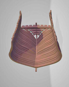
a 3D model looks ok


aastern6.jpg
Turning the model still looks ok so far

aastern5.jpg

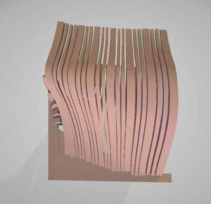
looking into the hull we see the backwards cant of the frames. The first problem becomes apparent look at the top of the frames the last frames are farther out than the rest. Something went wrong.

aastern2.jpg
 
Last edited:
Well your work is better than anything I could try to do.

Keep it up and I am sure with others help you will get it corrected.

The work done so far looks great.
 
getting into the nuts and bolts of the 3d build

I instructed the 3D model to be built like you would build the actual model that does not work and here is why
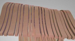
lineup.JPG

when the 3D hull is turned you can see the frames do not line up, they should follow the red line, close for some but not what it should be.
this is caused by issues I posted in #257

what the hull should look like is this
from green arrow to green arrow the hulls surface should be a smooth continuous surface where the front edge of a frame blends with the back of the frame that comes before it.

one way that might work is the model the hull as a solid and slice it at each frame.
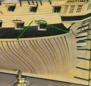
lineup1.jpg


here is another problem

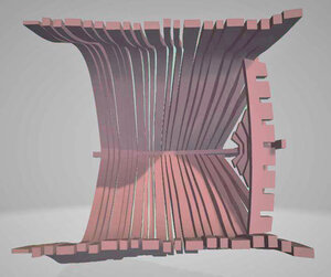
see all the frame sitting on the table in front of the hull, they are all flat there is no curve to them other than the shape of the frame itself
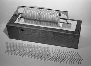
alfred13.jpg

taking frame Z as an example, that shape is not actually the shape of the frame that is showing the shape of the hull. It is hard to grasp from a mechanical drawing point of view
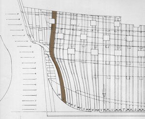
zshape.jpg

what happened when you remove frame Z from the 3D model it looks like this, it is bent to look like the above drawing and it should be flat.

excuse the poor rendering of the images they are just a sample.
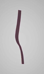
az frame1.jpg
az frame3.jpg
az frame4.jpg
az frame5.jpg

what gives the hull it's shape is the frames are flat and the cant (angle backwards) and the bevels on the outer and inner surfaces shape the hull from frame to frame

so it is back to the drawing board
 
Back
Top