Cad design Alfred stern cad designing

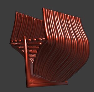
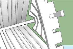
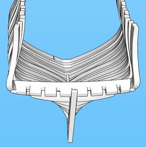
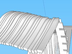
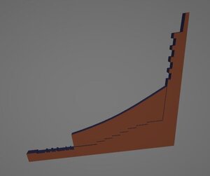
Oops I think I broke it :eek:

framesw2-XL.jpg


The model looks good in Solidworks, by the way.
 
It looks like an inflatable ship frame to me. This is just a guess, but I'm thinking it's a setting the texturing part of your software. I don't know anything about the software you're running, but from my years working on computers when video cards don't work adequately they don't typically produce a fully rendered image. I'm thinking it's rending it out of rubber or something like that.
 
It looks like an inflatable ship frame to me. This is just a guess, but I'm thinking it's a setting the texturing part of your software. I don't know anything about the software you're running, but from my years working on computers when video cards don't work adequately they don't typically produce a fully rendered image. I'm thinking it's rending it out of rubber or something like that.


i posted on the Fusion360 forum and got 47 views and no replies as to why the rendered model looks that way not even a suggestion. Well so much for help and support from fusion360.
i ruled out anything wrong with the file because you guys do not have a problem with it. So it comes down to some setting in the program or the computer. The thing is i have a laptop and a desk top with fusion 360 on them and i get the same results from both.

here is what is recommended for fusion360

Graphics Card Supported for DirectX 11 or greater
Dedicated GPU with 1 GB or more of VRAM
Integrated graphics with 6 GB or more of RAM
Disk Space 3 GB of storage
Display Resolution 1366 x 768 (1920 x 1080 or greater at 100% scale strongly recommended)
 
Just a wild shot in the fog, have you checked if you have the latest driver for your video card? Especially if you are running an insider version of windows it could perhaps happen that M$ release an update that screws up the communication with certain hardware.

Running Dxdiag could perhaps reveal if directx functions are working properly.

Strange though, that you are having the same issue on 2 diiferent computers
 
Last edited:
Just a wild shot in the fog, have you checked if you have the latest driver for your video card? Especially if you are running an insider version of windows it could perhaps happen that M$ release an update that screws up the communication with certain hardware.
Nah...Dave is running software on Windows 98 :D Everything will be fine...
 
i did have a meeting with my computer geek friend. It is always nice to have at least one friend who is a geeky kind of guy yes a little weird but i can deal with that. Anyhow it seems the issue is a bad video card so the computer is undergoing repairs. hope that solves the issue.

hey don't be talking trach about windows 98 actually i am running it on the computer that runs the plotter also running windows 7 and windows 10 pro.

some programs are 32 bit and others are 64 bit so to run everything you need more than one computer. i never retire a computer i just demote it to other tasks like a huge back up library or running a plotter some stay off line and dedicated to one task
 
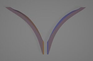
Mohamed and i are approaching the 3D model one step at a time here is the deadwood. you will notice the deadwood is modeled in one piece in the real ship the deadwood is made up of several pieces. We want an overall model not all the bits and pieces

deadwood stl.JPG

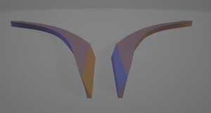
here is the fashion timber notice it has an extreme bevel

fashion timber1.JPGfashion timber2.JPG
 
i did post STL files so anyone can view them in windows 3D viewer and seems no one is interested no feed back other than 2 members out of over 4,000 members. so i did not post the STL files for the deadwood or fashion timber.

there were no replies from anyone trying to view the files in windows 3D view so i do not know if it is working for people or not. either this has no interest or it is over the heads of members and too geeky maybe.
 
I'm a little lost here. Perhaps it is due to my ignorance but I do not understand the purpose of making a 3D model if you don't want to create the individual parts. I much assume the purpose cannot IRL production then? And even if it the purpose should be learning I don't think I get it. I mean, couldn't it just as well be a solid hull then?
 
there are 2 topics going on about 3D modeling and design one here and one at MSB. The MSB topic gets into more tech details.
the 3D model is infact made up of parts that are assembled into a final model. some parts are not 3D modeled because the fabrication is done from a 2d CAD drawing.
 
The error you were getting looks like the mesh normals were smoothed, which is a common error I see with CAD models I receive for work, so I'm surprised that replacing the graphic's card fixes it. I was able to reproduce it in Blender by setting the object to Shade Smooth.
Annotation 2020-08-28 233808.jpg
I'm unfamiliar with the software you are working in though, so I'm not sure I can recommend how to fix it.
As for 3D Modelling the frames, I had similar alignment issues on my 3d model of HMS Enterprise (which is not being modeled for printing which allowed me to just fudge it a bit). Modelling the frames as a continuous hull and then slicing them apart is probably how I would handle it. It seems to work really well on this guy's CAD model of HMS Pandora.
 
The error you were getting looks like the mesh normals were smoothed, which is a common error I see with CAD models I receive for work, so I'm surprised that replacing the graphic's card fixes it. I was able to reproduce it in Blender by setting the object to Shade Smooth.

actually after upgrading the graphic card did not fix the problem so i concluded it is not hardware it is some setting in fusion360. Because i am new to fusion360 only a few months into it i do not know my way around the program.
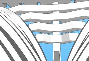
right now i am working on a few drawing issure first of all the lower transom ends should rest against the fashion timber which they don't the notches in the wing transom go all the ay through which is wrong. And the frames do not line up as they should. also the notches are to wide for the inner stern post


this is the same STL file but in a different program and as you can see there is no rendering issue like i am seeing in fusion360

trans1.JPGtrans2.JPGtrans3.JPGtrans4.JPGframe bevels1.JPG
 
I'm looking for either a .stl file of the stern galleries of an East India company ship or the same area of any large ship of that era to create a new stern for the Monogram model of the Bonhomme Richard. I don't know where Monogram got the idea for the stern galleries of that model but they don't resemble that area of any ship of that era I have ever seen. Now that I have a 3D printer that has become one of my goals,
 
there were a few issues with the modeling of the Alfred stern first problem was the poor rendering of a STL file in Fusion 360. a raw STL file has to be converted and Fusion 360 does not like to many faces that make up a surface. Actually Fusion loves to show IGS files which you are now looking at.

another issue is you have to be exact with a CAD drawing to begin with because as soon as you use a 2D CAD file to build a 3D model all the errors begin to show up.

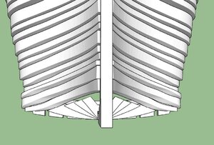
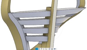
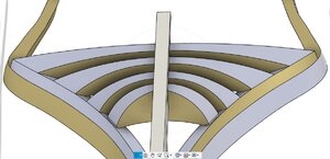
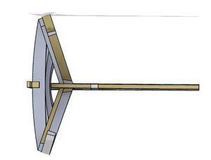
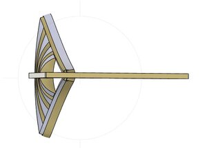
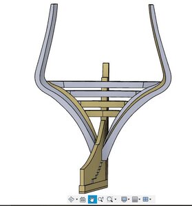
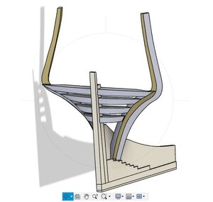
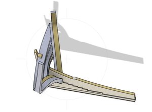
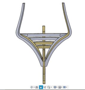
so lets take a look this model shows the keel, deadwood, frame Z the fashion timber and the lower transoms. On the original admiralty drawing 9 transoms are shown, that does not mean that is actually how the ship was built, the drawing is just a suggestion construction depended on the master shipwright in the yard and what materials were at hand. Harold Hahn drew 4 transoms to simplify construction so model builders are able to build a model or perhaps he had research material that suggested any number of lower transoms could be used. At any rate the 3D model is reconstruction of the model Harold Hahn drew and built so the 3D model will remain faithful to Harold's work

there are a couple more "tweaks" to be made before moving on to the main wing transom.

alfred stern 9 21a.JPGalfred stern 9 21b.JPGalfred stern 9 21c.JPGalfred stern 9 21d.JPGalfred stern 9 21e.JPGalfred stern 9 21f.JPGalfred stern 9 21g.JPGalfred stern 9 21h.JPG.
 
BTW I am very willing to pay a reasonable fee for a stern galleries stl file or multiple stl files.


there is a tech group made up of members from this and other forums that is just shop talk on 3D modeling CAD drawing, 3D printing, and fabrication. It is by invite only and can be a bit boring if you not into the tech side of the hobby.

The Alfred is a result of the work of the tech group the Alfred CAD drawings are done by me the modeling is done by Mohamed so it is a combined effort.
 
Back
Top