Cad design Alfred stern cad designing

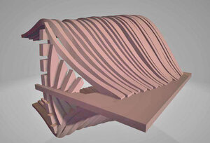
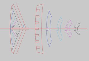
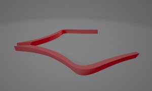
what gives the hull its shape is the bevels inside and outside of the frame the trick here is that bevel is fluid and changes from the bottom to the top of the frame which you can see in this cross section at 2 locations on the frame

another issue with drawing it is rare these bevel lines are exact because they may slightly change when a frame is installed into the hull. model builder will give the hull a final sanding to match all the frames in a smooth continuous surface.
problem you can not sand a 3D model to a final shape
cross section.JPG
 
Last edited:
actually I am pondering why that bent z frame works in the 3D hull when it reality it is flat, how does it work both ways? something to say hum about

at this point i have first the original Hahn drawing then the CAD drawing, the CNC and cutting file drawings and the 3D modeling drawings and at this point they do not seem to play nice together
 
Last edited:
this takes a lot of work to figure this out not only what to do but how to do it

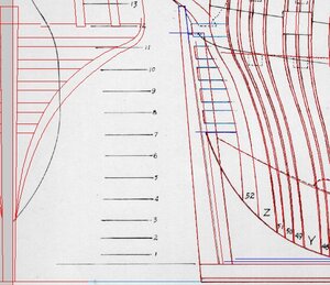
getting back to the 3D model and fitting problems those wing transoms should rest against the fashion timber the last frame #52 which sits against frame Z

what looks wrong is first off frame 52 sets against frame Z the angle of the frames may not be correct and 52 and Z actually have more of a "cant" or angle

aastern8.jpg

here is the drawing and they are drawn so the forward ends are against frame #52

transoms1.JPG

projecting the shape they are drawn to set against frame #52

transoms2.JPG

here they are in the model
ded1.jpg

transoms3.jpg

transoms4.jpg
 
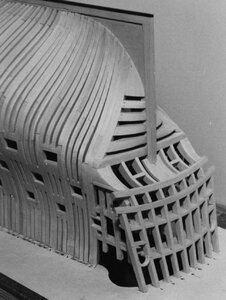
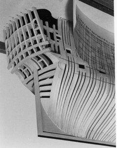
there were problems figuring out how to build a hull as a 3D model

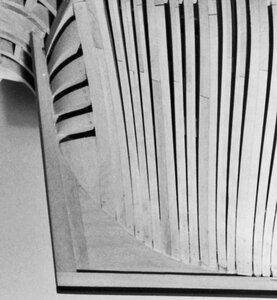
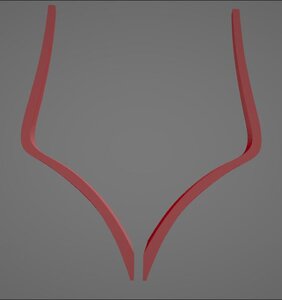
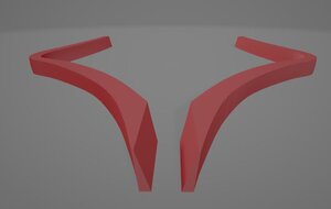
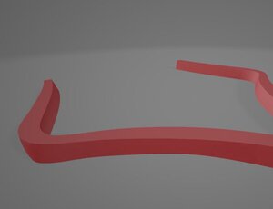
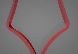
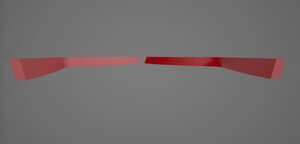
Mohamed and i went back to square one and modeled just one frame to work out the issues. first there were the bevels and the angle of the foot where it sits against the deadwood. you can see the bevels in the images. Now that one frame was modeled successfully we can proceed to the rest of the frames

frame z1.JPGframe z2.JPGframe z3.JPGframe z4.JPGframe z5.JPGframe z6.JPG
 
the idea behind 3d modeling is to use the model as an instruction so a builder can look at the model from all angles and see how parts fit together, also for a model builder to screen capture a view to question a part or how it fits.

this is a test on using 3D models you will find STL files attached
These files can be opened in several 3d programs such as Fusion360, Sketchup, solidworks and others.

to view a 3D STL file Windows 10 has a built in program 3D view so anyone can view a model if they are using windows10

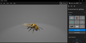
3D view opens to this screen

3dv.JPG

go to open and open the STL file

3dv1.JPG

it will show as gray on gray

3dv1.JPG

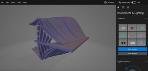
to the right you can click on the themes to change the color of the model as you get use to the program things like lighting and color can be changed

3dv2.JPG


the model you are looking at is just a test file there are to many errors in the actual model to be used for anything other than a demo.

you can rotate the model as well as zoom in and out As 3D models become more complex and more detail is added they will aid in actual model building because you can view every part and how it fits in the model.

so give it a try and let me know how it works for you, post different views if you want
 
Dave

learning CAD is a long winded process. It was part of my art training way back in the early 70s and it took hundreds of hours over years and i am still learning.
Actually i started with a drafting table, T square and pen and ink and learned the basics in industrial design. There are rules and methods drafting of plans and layout that must be followed so your drawing can be understood by any other draftsman who picks up the drawing, or a fabricator has to be able to read what you are trying to do. The transition from table to computer was an easy step because of the training in the basics.
Where the glitch came in is learning ship construction and design.

I hear you, Dave! Life comes down to choices. I was cutting up cadavers about then! It was my choice, so I can’t complain. Still, I wish NOW that I‘D learned CAD!
 
one teacher from my days in industrial arts and pattern making made it easy to understand there is drawing like sketching an object and there is mechanical drawing and that is imbedding "instructions" in the drawing.
 
Dave

learning CAD is a long winded process. It was part of my art training way back in the early 70s and it took hundreds of hours over years and i am still learning.
Actually i started with a drafting table, T square and pen and ink and learned the basics in industrial design. There are rules and methods drafting of plans and layout that must be followed so your drawing can be understood by any other draftsman who picks up the drawing, or a fabricator has to be able to read what you are trying to do. The transition from table to computer was an easy step because of the training in the basics.
Where the glitch came in is learning ship construction and design.
Perhaps it would be easier if English, my mother tongue, was used instead of gobbledegook, double-dutch and foreign jargon, that you tech. geniuses use when discussing CAD,rendering and related subjects.
 
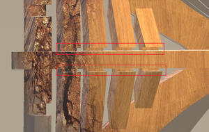
I join awesome choir :) I have no clue about the proper ship term but are some of the dados at the stern (red squares) not too wide?

View attachment 174222

very good PoulD you found one of many errors in the drawing

yes this STH file has many errors in it and it is just being used as a demo so members can play around with viewing a 3D model.

Actually what you are doing is what i hoped members would do and view the 3D model to find errors or questionable flaws.

there is a new drawing in the works and errors and problems are being corrected.


this all comes down to accurate CAD design work if the original CAD work has flaws they will be carried on to the 3D modeling.


by creating a 3d model from a CAD design does bring out errors that may have been overlooked.
 
Back
Top