-

Win a Free Custom Engraved Brass Coin!!!
As a way to introduce our brass coins to the community, we will raffle off a free coin during the month of August. Follow link ABOVE for instructions for entering.
-

PRE-ORDER SHIPS IN SCALE TODAY!
The beloved Ships in Scale Magazine is back and charting a new course for 2026!
Discover new skills, new techniques, and new inspirations in every issue.
NOTE THAT OUR FIRST ISSUE WILL BE JAN/FEB 2026
You are using an out of date browser. It may not display this or other websites correctly.
You should upgrade or use an alternative browser.
You should upgrade or use an alternative browser.
Artesania Latina Anatomy of Lord Nelson’s HMS Victory 1805
- Thread starter AlanOES
- Start date
- Watchers 39
-
- Tags
- artesania latina victory
- Joined
- Nov 30, 2024
- Messages
- 156
- Points
- 103

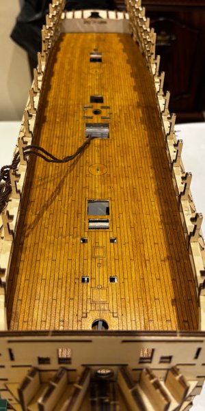
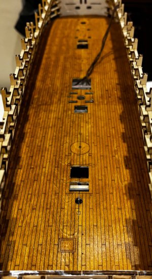
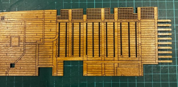
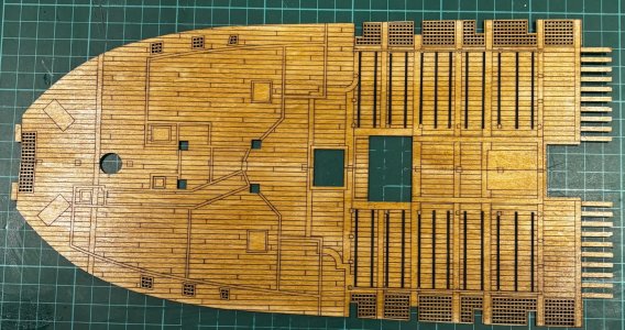
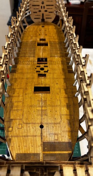
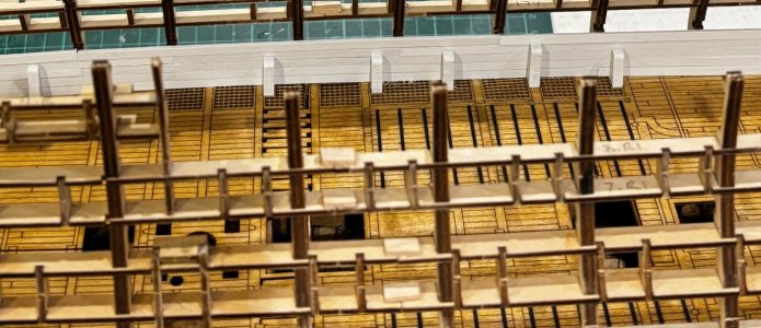
Instructions video #10 completed
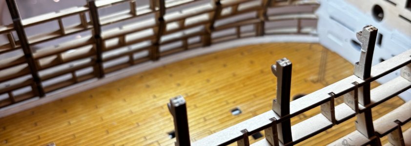
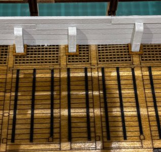
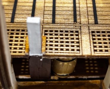
Not overly happy with the deck joints
I have to assume that my framing is slightly out but a straight but joint would have been easier to resolve than all those interlinking planks. Felt it was more important to get the mast holes and deck openings lined up properly which left the planking joints a bit out of line. Don’t want to try filling the gaps as I think that would draw attention to it
Hopefully the next deck will be better as it doesn’t have all those upright beam cut outs to align up as well


- Joined
- Nov 30, 2024
- Messages
- 156
- Points
- 103

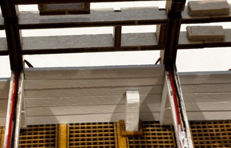
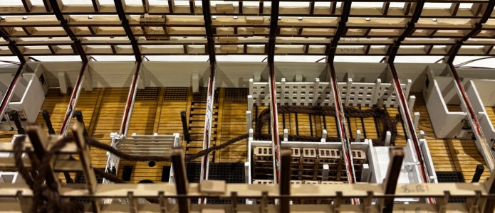
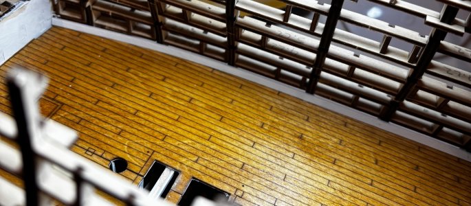
Instructions video #13 completed
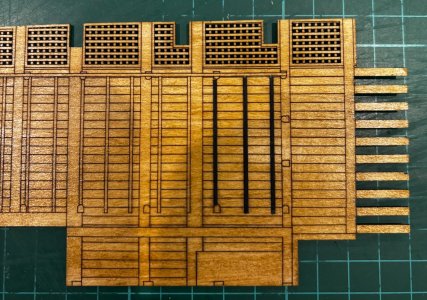
A couple of points on this one. They don’t show you in the video but to fit the foreword port knee you need to cut a slot in the side planking. Also they don’t give you the part numbers for the 3 grilles on the orlop deck
For anyone doing this build they are parts O24 A, B and C on sheet 27
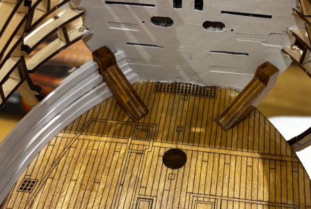
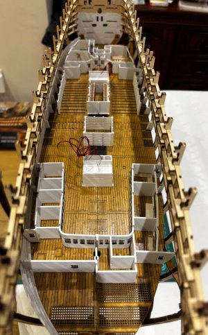
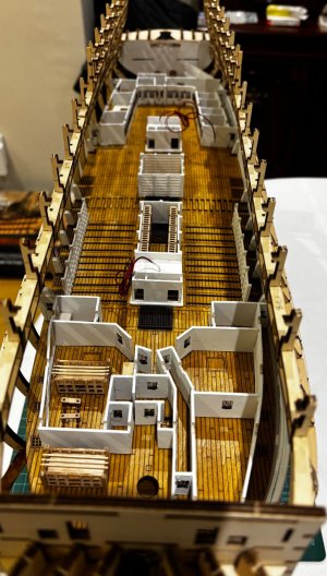
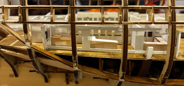
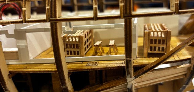
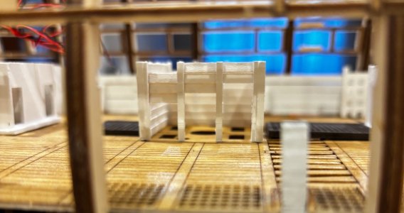
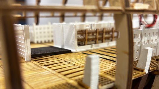
A couple of points on this one. They don’t show you in the video but to fit the foreword port knee you need to cut a slot in the side planking. Also they don’t give you the part numbers for the 3 grilles on the orlop deck
For anyone doing this build they are parts O24 A, B and C on sheet 27


- Joined
- Nov 30, 2024
- Messages
- 156
- Points
- 103

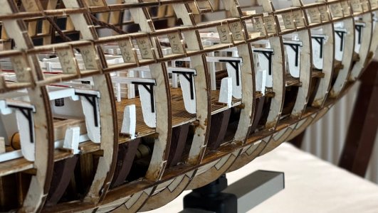
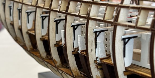
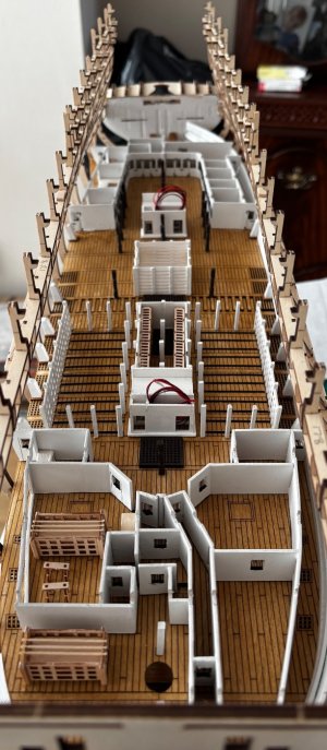
Instructions video #14 Part 1 completed
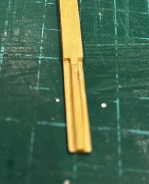
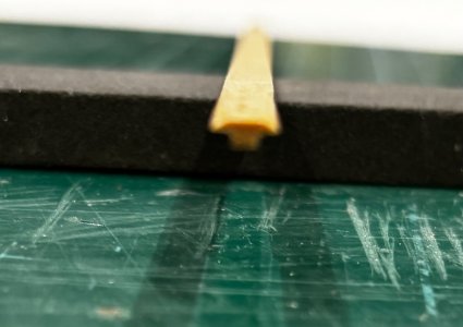
There’s a lot of work to be done in this video so I’ve decided to post it in 2 parts to avoid an overly long post with too many pictures
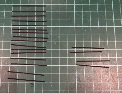
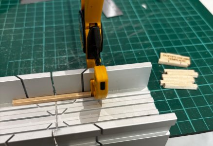
Another omission on this one, the video doesn’t show the fitting of the 2 square pillars at the stern although they are noticeable later in the video. For those that need to know, one is 24mm high like the majority of the others but the stern most one sits under deck beam #16 so has to be 21mm high
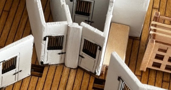
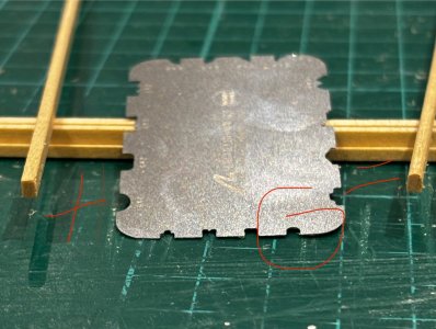
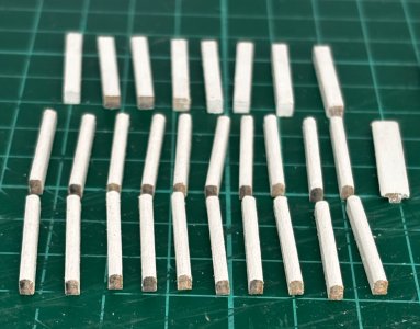
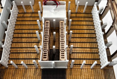


Hi Alan
Tony from Brisbane here.
After 40 odd years of plastic I will give the dark side a crack. About 5 years ago I bought AL’s San Francisco II out of pure curiosity, took it to planking stage before shelving it when we moved house. I recently revisited her and made some canon (will get to that planking).
I’m originally from Durham and occasionally return to Blighty to see family. However in September my wife and I are embarking on a Mediterranean cruise after a week in the UK. During our visiting we are catching up with friends in Portsmouth. This is where I get to my point. I will be going to tour the HMS Victory, which I’m so excited for. While watching many utube clips of the ship my wife said, “you should build a model of that”. I thought maybe one day, and thought no more of it. Then to my surprise as a retirement present I was generously gifted “Artesania Latina HMS Victory Anatomy Version”. What a gift!
Yes, yes, yes as this will only end up being my second ever wooden ship I will do doubt be well out of my depth. But at 62 I needed a new challenge and a long- term project.
I note that you too are well on your way with this build, wonderful work so far Mate. Not sure when I will start her (got to finish the San Francisco) but in the meantime I will follow along with your build with great admiration. I for one love the video instructions and have watched up to 50 odd so far. I hope you don’t mind the odd question, I’m sure I will have a few.
Cheers Tony
- Joined
- Nov 30, 2024
- Messages
- 156
- Points
- 103

Hi Tony,Hi Alan
Tony from Brisbane here.
After 40 odd years of plastic I will give the dark side a crack. About 5 years ago I bought AL’s San Francisco II out of pure curiosity, took it to planking stage before shelving it when we moved house. I recently revisited her and made some canon (will get to that planking).
I’m originally from Durham and occasionally return to Blighty to see family. However in September my wife and I are embarking on a Mediterranean cruise after a week in the UK. During our visiting we are catching up with friends in Portsmouth. This is where I get to my point. I will be going to tour the HMS Victory, which I’m so excited for. While watching many utube clips of the ship my wife said, “you should build a model of that”. I thought maybe one day, and thought no more of it. Then to my surprise as a retirement present I was generously gifted “Artesania Latina HMS Victory Anatomy Version”. What a gift!
Yes, yes, yes as this will only end up being my second ever wooden ship I will do doubt be well out of my depth. But at 62 I needed a new challenge and a long- term project.
I note that you too are well on your way with this build, wonderful work so far Mate. Not sure when I will start her (got to finish the San Francisco) but in the meantime I will follow along with your build with great admiration. I for one love the video instructions and have watched up to 50 odd so far. I hope you don’t mind the odd question, I’m sure I will have a few.
Cheers Tony
Thanks for your comments, this is only my 2nd wooden ship build and I’m 73
Enjoying it so far, and yes feel free to ask any questions and I’ll try to answer them to the best of my ability
Regards
Alan
Brilliant effort!
A couple of things I note from the videos.
One, the guy doing the instructional videos extensively uses CA glue instead of what seems to be the norm of white glue and pinning etc. Maybe it's a speed thing what's you view on this?
Two, video #7 Lighting. I know nothing about LED lights never had the need to use them in the time I built plastic models.But I have ordered a set. I noted that on just about every beam there are 2 lights each fed by a red/positive and black/negative wire, so 2 wires per light, 4 wires in total per beam each fed back through the hull. I'm OK with this so far. However when he gets to the small room to be lit by 2 lights (I think it's a powder room?) he takes a different approach. He joins the 2 lights together, presumably neg to neg pos to pos then attaches 1 red and 1 black light back through the hull, so only 2 wires to be fed through. My query is why does he not take the same approach with the beam lights (wire the two together) and only have 1 pair (not 2) of wires returning to the hull. Less wires? I can only think its easier to do it this way in the channels carved in the beams maybe?
Thanks for your thoughts.
Regards
Tony
- Joined
- Nov 30, 2024
- Messages
- 156
- Points
- 103

Hi Tony
Yeah, the glue is for speed, I think they mention that in the question section of one of the early videos.
I’m following that lead and using industrial CA, you can get it in various thicknesses to suit what you need to do and can also get activator spray to make it go off even faster, just means you can progress faster (it’s a long project and I’m not getting any younger lol ) but it’s a personal choice I guess.
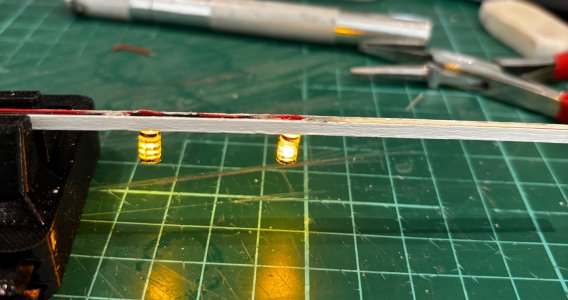
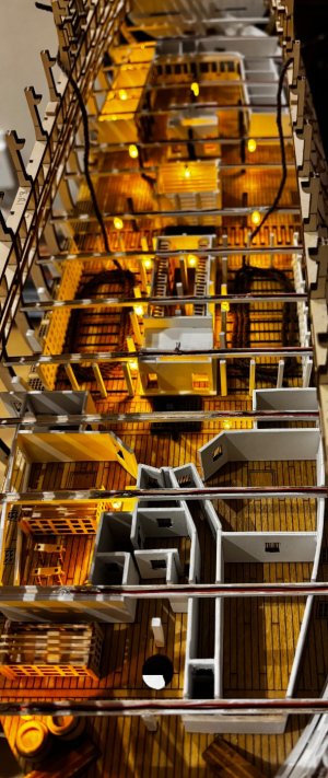
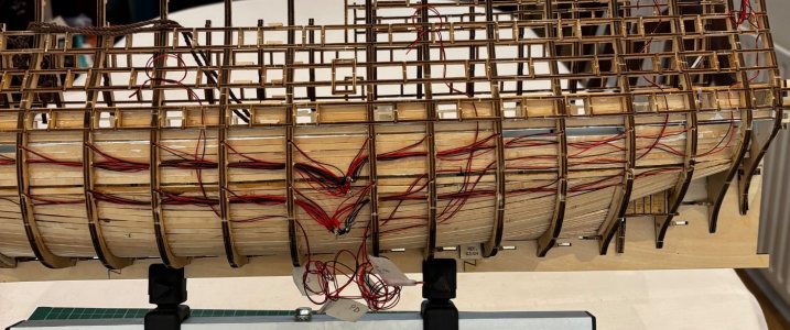
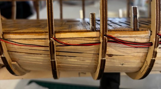
The led lights as you mention, he joins two together only because that would mean 6 wires in the channel otherwise, he never joins them ON the beam. But I actually have, as you say, a lot less wires to deal with, you need to be fairly neat with the soldering so the join stays within the channel, also, the led’s are polarity sensitive (long leg positive) so make sure you don’t mix them up as there is a case where the two led’s are close together and the legs need to be cut to avoid shorting, my method is to always have the positive leg to the port side of the ship. I also glue the joints/cables down in the groove as they have a tendency to spring up a bit. I’ve actually just finished doing the led’s on the orlop deck
Hope that helps
Regards
Alan

Last edited:
Hi Alan
Thanks for the help. Yes CA will speed things up I will probably go the same way (for most of it). Even at 62 I don't want to hang-around.
Yep I thought as much with the lights. I may try one beam using the 2 wire method but if it too fiddly I will follow the instructions. Thanks for the pic of your wiring, most helpful.
Regards
Tony
- Joined
- Sep 21, 2023
- Messages
- 33
- Points
- 68

Hi friends!
CA glue was used, as you said, because it allows faster working. Imagine the difference in time we have in the creation of a prototype using CA or wood glue... Also notice CA glues today are not what they used to be, some years ago CA produced a lot of fumes and fragile joints; nowadays our modellers don't see a big difference between new, dense CA formulas for porous materials and classical wood glue, but the work is faster.
Regarding the LEDs, in the lower level of beams a pair of wires for each LED was used just because the space between inner and outer planking is bigger, allowing to work with those wires with no problem. You can work in the lower level with a pair of wires per beam, connecting the LEDs in parallel circuit as we did in upper levels, it's not a problem.
Best regards from Spain!
Thank AL for info
Splendid work Alan, well done with those bracing bars. Definitely more fiddly work and no doubt more to come. 
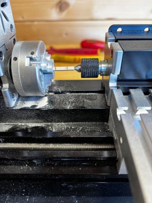
I think investment in a mini lathe for the posts and tapering dowels maybe a wise investment. I'm ploughing on with the San Francisco will try to put some pics up when I complete the first planking.

I think investment in a mini lathe for the posts and tapering dowels maybe a wise investment. I'm ploughing on with the San Francisco will try to put some pics up when I complete the first planking.
Hi Alan
I note that on the instruction video #14 at about 4.50 the wiring on beam B14 does not travel through the whole beam it is re-routed around the adjacent curved back wall. I though this maybe to accommodate another light in that area but it does nor appear to. Any idea why this is done that way?
Regards
Tony
Oh yes I understand
Regards
T
Regards
T
What a fantastic build! This is a great kit. You've made the interior so well!

