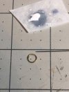
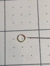
I get it, however your wheel is actually too small for the scale…it could have been 6-7mm in diameter and be ok. And you could still add the bumps. I was demonstrating the technique with what I had and did it in about 30 minutes, as I don’t have a lot of spare time. I am currently building my ship and have the upper galley and 20 cannon carriages I’m working on. Otherwise I would build a wheel at 6mm and demonstrate. And still might…lol…because I like a challenge. I would use a needle point to add the glue. So stay tuned…if I have time this evening I may just give it go…...an enormous...
View attachment 513986
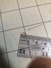
That rule at the top is graduated in millimeters, not inches. Your dots need to go into a 1.7mm space between the spokes.
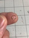
View attachment 513993View attachment 513988
And compare the sizes of our index fingers and our wheels - "disregarding scale" indeed.
Now do one my size (and as fragile).
I knew you were shooting a line.
-

Win a Free Custom Engraved Brass Coin!!!
As a way to introduce our brass coins to the community, we will raffle off a free coin during the month of August. Follow link ABOVE for instructions for entering.
- Home
- Forums
- Ships of Scale Build Logs
- Super Detailing Static Models / Other Genres
- Historical Trailways, Guns, Aircraft, and Cars
You are using an out of date browser. It may not display this or other websites correctly.
You should upgrade or use an alternative browser.
You should upgrade or use an alternative browser.
Avro Anson Mk.1 - Plastic by Airfix in 1/48 Scale - Build by Smithy
- Joined
- Dec 3, 2022
- Messages
- 1,547
- Points
- 488

I still think it’s doable
Good luck with that. And no 3D printing. You’ve got to make it the same way I did for any comparison to be valid. It’s as fragile as a ladybird’s wing so mind how you sand it.


Yes, I said it was a little underscale at the time. Close enough though.
I will show the assembly…may use wire…no sanding needed.Good luck with that. And no 3D printing. You’ve got to make it the same way I did for any comparison to be valid. It’s as fragile as a ladybird’s wing so mind how you sand it.

Yes, I said it was a little underscale at the time. Close enough though.
- Joined
- Dec 3, 2022
- Messages
- 1,547
- Points
- 488

I will show the assembly…may use wire…no sanding needed.The material used doesn’t matter if it’s painted…plastic, wood or metal are all good.

Yes it does. We are disputing the possibility of adding bumps to my wheel which I assert is impossible due to its geometry and fragility. You said you could sand it too, I think.
If you make one out of wire, you have a completely different set of circumstances.
Why don’t we just drop it? This piddling contest is spoiling the ambience of my thread and wasting your cannon building time.
I’ll pretend to believe you and you pretend to have won.

Last edited:
Well, it’s not about winning, modeling is not a contest to me. I was suggesting a technique to add detail and realism. You claim it’s not possible. And furthermore you want to limit my attempt to using your construction methods.Yes it does. We are disputing the possibility of adding bumps to my wheel which I assert is impossible due to its geometry and fragility. You said you could sand it too, I think.
If you make one out of wire, you have a completely different set of circumstances.
Why don’t we just drop it? This piddling contest is spoiling the ambience of the thread.
I’ll pretend to believe you and you pretend to have won.
So let me say this, any criticism I offer is always constructive criticism and not meant to offend anyone.
That said, when I scratch build, nothing is off limits as far as materials and technique. I would consider many approaches. One, build it out of wood and carve from one piece, giving it more structural integrity. Two start with hub and drill holes and add wire, giving it more strength, then glue the handle to the wire. Possibly even use small shielded wire for the handle. Many possibilities and approaches!
The glue added with a needle would be small enough. I think you hurt your chances by making the wheel 4mm instead of 6mm. You could also exaggerate the angle between the spokes to give yourself more room for a longer handle. So many ways to skin a cat!
In closing, I applaud your efforts and what you have is certainly acceptable. However I guarantee you a 6mm wheel could have the bumps added. And the material you add the glue to will not affect the ability to do so whatsoever and you don’t have to sand anything to add bumps either, so fragility does not come into play either.
So just get some magnifying glasses, PVA and a needle! You can do it!

If nothing else, I hope I shared a technique to be used in the future! Cheers mate!
- Joined
- Dec 3, 2022
- Messages
- 1,547
- Points
- 488

Well, it’s not about winning, modeling is not a contest to me. I was suggesting a technique to add detail and realism. You claim it’s not possible. And furthermore you want to limit my attempt to using your construction methods.
So let me say this, any criticism I offer is always constructive criticism and not meant to offend anyone.
That said, when I scratch build, nothing is off limits as far as materials and technique. I would consider many approaches. One, build it out of wood and carve from one piece, giving it more structural integrity. Two start with hub and drill holes and add wire, giving it more strength, then glue the handle to the wire. Possibly even use small shielded wire for the handle. Many possibilities and approaches!
The glue added with a needle would be small enough. I think you hurt your chances by making the wheel 4mm instead of 6mm. You could also exaggerate the angle between the spokes to give yourself more room for a longer handle. So many ways to skin a cat!
In closing, I applaud your efforts and what you have is certainly acceptable. However I guarantee you a 6mm wheel could have the bumps added. And the material you add the glue to will not affect the ability to do so whatsoever and you don’t have to sand anything to add bumps either, so fragility does not come into play either.
So just get some magnifying glasses, PVA and a needle! You can do it!
If nothing else, I hope I shared a technique to be used in the future! Cheers mate!
Whatever.
- Joined
- Dec 3, 2022
- Messages
- 1,547
- Points
- 488

Despite my own leading part in the vagabond nature of this thread, I'd like to get the build and log back onto the topic of the model Anson. The last two or three pages have meandered into something that will surely be quite tedious for anyone reading later and not currently involved in the chattering.
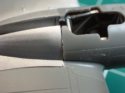
Yesterday, in between the gossip, I paid some attention to the model. I've realised that I made a tactical mistake when I decided to postpone seam tidying of the various assembly stages until the end. I've always done this because it's a job that I don't enjoy but the result of my procrastination is that eventually I must tackle a BIG job that I dislike, rather than several small sessions. Fancy only discovering this at the end of a lifetime's modelling. Oh well, the lesson has been learned now, though possibly forgotten later.
That gap in the engine fairing is horrid and clearly inaccurate. Putty is no good for something like that because it always shrinks a little and when sanded, it becomes rounded and just looks a mess. It's also difficult to re-scribe detail into putty and it flakes away at the edges. In short, old-style putty is nasty and I no longer use it at all.
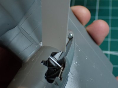
The best thing to fill a big gap in plastic is plastic. I find a suitable thickness of plasticard, slightly larger than the gap, then widen the gap to fit the card perfectly. I apply a drop of TET either side and let it set. This won't shrink. It has structural strength and won't crack. It sands at the same rate as the plastic of the kit and scribes in exactly the same way too.
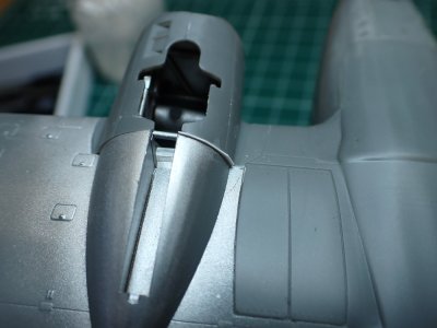
When it's set, I trim the excess with scissors and sand.

That will do. Excuse the water and dust.
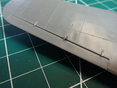
I worked my way around the wings, sanding my self induced misalignment (or was that one Airfix?). The ailerons required a bit of fettling as their housings were affected by the disarranged wing halves. I shaped the ailerons to fit the gap and the gap to fit the ailerons and ended up with something reasonable.
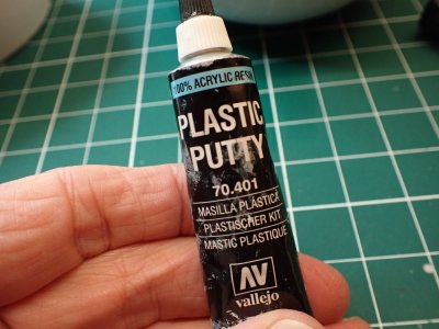
Returning to the gap filling, I tackled the smaller crevices with this type of putty. It's a thick liquid with no grit as you find in old-fashioned putty. It flows into the gaps and then the excess can be immediately wiped away with a moist cotton bud/Q-tip; there's no sanding to do! I moisten my cotton bud with spit because the sliminess of saliva gives a smoother finish. That might be too much information for the faint-hearted.
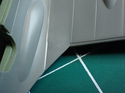
With conventional putty filing that cranny in the hollow of the wingroot would be a right pain in the neck. With acrylic resin, no problem. It does shrink a tiny bit but on this model in this position on the airframe, I don't care. It's a panel line.
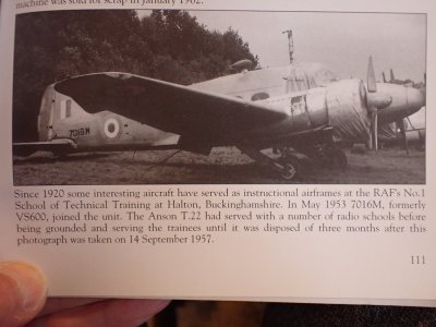
Here's a picture for @Alan Smith . It won't be one of the Ansons that your brother worked on in the 40s but it is one of the Haltom instructional airframes and I thought you might be interested. It's not as tidy as we thought after four years in the hands of the trainees and out in the weather.
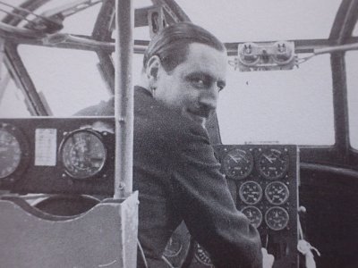
And finally... "Hello Popsy. Fnaah fnaah! How about we fly over to Paris for the weekend while your husband is away?"

Yesterday, in between the gossip, I paid some attention to the model. I've realised that I made a tactical mistake when I decided to postpone seam tidying of the various assembly stages until the end. I've always done this because it's a job that I don't enjoy but the result of my procrastination is that eventually I must tackle a BIG job that I dislike, rather than several small sessions. Fancy only discovering this at the end of a lifetime's modelling. Oh well, the lesson has been learned now, though possibly forgotten later.
That gap in the engine fairing is horrid and clearly inaccurate. Putty is no good for something like that because it always shrinks a little and when sanded, it becomes rounded and just looks a mess. It's also difficult to re-scribe detail into putty and it flakes away at the edges. In short, old-style putty is nasty and I no longer use it at all.

The best thing to fill a big gap in plastic is plastic. I find a suitable thickness of plasticard, slightly larger than the gap, then widen the gap to fit the card perfectly. I apply a drop of TET either side and let it set. This won't shrink. It has structural strength and won't crack. It sands at the same rate as the plastic of the kit and scribes in exactly the same way too.

When it's set, I trim the excess with scissors and sand.

That will do. Excuse the water and dust.

I worked my way around the wings, sanding my self induced misalignment (or was that one Airfix?). The ailerons required a bit of fettling as their housings were affected by the disarranged wing halves. I shaped the ailerons to fit the gap and the gap to fit the ailerons and ended up with something reasonable.

Returning to the gap filling, I tackled the smaller crevices with this type of putty. It's a thick liquid with no grit as you find in old-fashioned putty. It flows into the gaps and then the excess can be immediately wiped away with a moist cotton bud/Q-tip; there's no sanding to do! I moisten my cotton bud with spit because the sliminess of saliva gives a smoother finish. That might be too much information for the faint-hearted.


With conventional putty filing that cranny in the hollow of the wingroot would be a right pain in the neck. With acrylic resin, no problem. It does shrink a tiny bit but on this model in this position on the airframe, I don't care. It's a panel line.

Here's a picture for @Alan Smith . It won't be one of the Ansons that your brother worked on in the 40s but it is one of the Haltom instructional airframes and I thought you might be interested. It's not as tidy as we thought after four years in the hands of the trainees and out in the weather.

And finally... "Hello Popsy. Fnaah fnaah! How about we fly over to Paris for the weekend while your husband is away?"
Last edited:
Not sure why you so despise seam-tidying so much when you make it look so effortless.
- Joined
- Dec 3, 2022
- Messages
- 1,547
- Points
- 488

Not sure why you so despise seam-tidying so much when you make it look so effortless.
Maybe because a seam is a seam is a seam and it seems like there have been so many thousands of them over my career (headlong rush) in plastic. I hate being bored!
- Joined
- Mar 22, 2024
- Messages
- 396
- Points
- 168

@ Smithy You remarked about seeing some of the work of former apprentices on your visit to RAF Halton. My brother, who suffered there, was a genius with a file and i am forever grateful he taught me some of the filing skills he learnt there. Apparently one early task was to file a perfect 1" cube from a scrap of round bar, When you had done that you made - with hot metal and a cold chisel - a flat file for yourself, and then used it to re-make your cube into a perfect pyramid with the same height and base size. Mind boggling.
"They made their own micrometers back then while I struggled to hand file a simple brass rectangle to a tolerance of diddley squat. "
"
"They made their own micrometers back then while I struggled to hand file a simple brass rectangle to a tolerance of diddley squat.
 "
"- Joined
- Dec 3, 2022
- Messages
- 1,547
- Points
- 488

Not sure why you so despise seam-tidying so much when you make it look so effortless.
“Despise”? Am I moaning that much? Probably, but that’s due to causes other than modelling. I will endeavour to be more positive.
@ Smithy You remarked about seeing some of the work of former apprentices on your visit to RAF Halton. My brother, who suffered there, was a genius with a file and i am forever grateful he taught me some of the filing skills he learnt there. Apparently one early task was to file a perfect 1" cube from a scrap of round bar, When you had done that you made - with hot metal and a cold chisel - a flat file for yourself, and then used it to re-make your cube into a perfect pyramid with the same height and base size. Mind boggling.
"They made their own micrometers back then while I struggled to hand file a simple brass rectangle to a tolerance of diddley squat."
Fortunately for me it was being realised by 1974 that such high standards were entirely useless to electricians and our ‘hacking and filing’ training only lasted a month or so. Nevertheless, when I’m building ships I am grateful for that old basic engineering tuition.
Last edited:
- Joined
- Dec 3, 2022
- Messages
- 1,547
- Points
- 488

Happy Chocolate Holiday to All!
I've spent a couple of sessions on the transparencies with the pleasant result that the model is now looking quite Ansonish. (Turret and engines are not yet attached permanently.)
![P4180031[1].JPG P4180031[1].JPG](https://shipsofscale.com/sosforums/data/attachments/498/498173-035235c21d89c56d34237da116b6315e.jpg?hash=p7Pd11Nl6S)
There's a lot of glass in this bird! Clear polystyrene is always brittle and unforgiving so it's been a time to be careful.
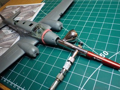
One danger is that the fumes from polystyrene cement might fog these crystal clear windows. I used the minimum of TET but just in case, I made use of forced ventilation from my airbrush for a few minutes.

The fit of these complicated shapes was generally very good, needing only the occasional smear of putty.
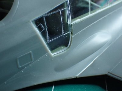
The one nasty gap was at the access door. If this was a full effort build I'd never have known as I'd have opened the door for the sake of extra interest. Never mind, I will simply declare that this particular aircraft had a bent door. (if any cowboy out there feels the need to tell me how much better their door would have fitted, please don't trouble yourself, ignore function invoked. )
)
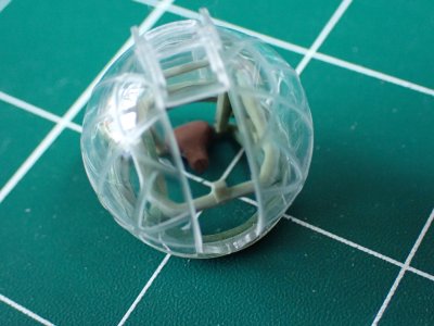
The turret supplied a bit of drama. The three parts of the transparency are assembled onto the base framework and also glued to each other. Fortunately, I decided to do this in one go so that I could nudge the pieces together for a good fit, before the cement set hard. It went well and I was just about to set it aside to dry when a thought struck me. I took a look and sure enough, I'd glued the perspex to the UNDERNEATH of the turret mechanism. This felt like a disaster for a moment as I pulled the base away but to my delight, the transparency remained solid and I was able to press it into place on the top side of the framing without difficulty.
I'll glue the gun in place after the masking and painting.
![P4180030[1].JPG P4180030[1].JPG](https://shipsofscale.com/sosforums/data/attachments/498/498181-5ec5502e9d95a38b121301855881b009.jpg?hash=Pl20l8JMsK)
I liked this little touch from Airfix which is a pretty good representation of the early forties landing lights. Isn't it horrible seeing these giant enlargements of brush painted details which are absolutely fine at real size!
Masking will be the next big job. I think I mentioned that I'd invested in a pre-cut mask set and I can't tell you how happy that's making me right now. Making 100+ window masks is the plastic aircraft equivalent of gun rigging on a 74.
I've spent a couple of sessions on the transparencies with the pleasant result that the model is now looking quite Ansonish. (Turret and engines are not yet attached permanently.)
![P4180031[1].JPG P4180031[1].JPG](https://shipsofscale.com/sosforums/data/attachments/498/498173-035235c21d89c56d34237da116b6315e.jpg?hash=p7Pd11Nl6S)
There's a lot of glass in this bird! Clear polystyrene is always brittle and unforgiving so it's been a time to be careful.

One danger is that the fumes from polystyrene cement might fog these crystal clear windows. I used the minimum of TET but just in case, I made use of forced ventilation from my airbrush for a few minutes.

The fit of these complicated shapes was generally very good, needing only the occasional smear of putty.

The one nasty gap was at the access door. If this was a full effort build I'd never have known as I'd have opened the door for the sake of extra interest. Never mind, I will simply declare that this particular aircraft had a bent door. (if any cowboy out there feels the need to tell me how much better their door would have fitted, please don't trouble yourself, ignore function invoked.

The turret supplied a bit of drama. The three parts of the transparency are assembled onto the base framework and also glued to each other. Fortunately, I decided to do this in one go so that I could nudge the pieces together for a good fit, before the cement set hard. It went well and I was just about to set it aside to dry when a thought struck me. I took a look and sure enough, I'd glued the perspex to the UNDERNEATH of the turret mechanism. This felt like a disaster for a moment as I pulled the base away but to my delight, the transparency remained solid and I was able to press it into place on the top side of the framing without difficulty.
I'll glue the gun in place after the masking and painting.
![P4180030[1].JPG P4180030[1].JPG](https://shipsofscale.com/sosforums/data/attachments/498/498181-5ec5502e9d95a38b121301855881b009.jpg?hash=Pl20l8JMsK)
I liked this little touch from Airfix which is a pretty good representation of the early forties landing lights. Isn't it horrible seeing these giant enlargements of brush painted details which are absolutely fine at real size!
Masking will be the next big job. I think I mentioned that I'd invested in a pre-cut mask set and I can't tell you how happy that's making me right now. Making 100+ window masks is the plastic aircraft equivalent of gun rigging on a 74.
Last edited:
Clever.I made use of forced ventilation from my airbrush for a few minutes.
- Joined
- Dec 3, 2022
- Messages
- 1,547
- Points
- 488

Clever.
I used to blow on them but these days it makes me dizzy.

I have to brace myself at the counter when using my inhaler.I used to blow on them but these days it makes me dizzy.

- Joined
- Mar 22, 2024
- Messages
- 396
- Points
- 168

I thought 'Brace yourself' was an Aussie code word for foreplay.I have to brace myself at the counter when using my inhaler.
- Joined
- Dec 3, 2022
- Messages
- 1,547
- Points
- 488

Bad news for Anson fans. With the majority of the construction finished and the exterior painting stage about to begin, Annie is now at a convenient point for me to take a leave of absence. Le Coquin is calling me. That's almost literally true; I woke suddenly at 02:30 wide eyed and exclaiming "Oh zounds! The Xebec! I should have..."
To find out what I should have done to my boat, and how I plan to sort out the mess, you'll have to follow me from the the skies above Dunkirk to the sunny Mediterranean shores of 1753.
To find out what I should have done to my boat, and how I plan to sort out the mess, you'll have to follow me from the the skies above Dunkirk to the sunny Mediterranean shores of 1753.
Last edited:
- Joined
- Dec 3, 2022
- Messages
- 1,547
- Points
- 488

I'm back and painting begins.
Painting begins ... with preparation. First, I donned rubber gloves. I won't touch the model with my fingers again until it's completely finished.
I degreased the entire surface of the model with IPA (India Pale Ale? No, isopropyl alcohol). This was to get rid of the fingerprints that I will have left everywhere. I wiped the larger surfaces with a paper towel soaked in IPA and then went over the windows with a soaked cotton bud to give the window masks their best chance of sticking.
Next, I had to mask the windows, and there are a lot of them. I mentioned before that I'd bought a set of pre cut masks made by Scale Mask and they were brilliant. They fitted really well, were sticky enough to hang on through lots of painting and handling but not so sticky that removing them for repositioning became difficult. They were thin and flexible so they stretched over compound curves but stiff and strong enough for me to be able to reposition them without them stretching out of shape. They also made masking the Anson a two hour job, with a break in the middle because my eyes were bleeding, instead of a week if I'd been cutting my own masks from Tamiya tape.
I enjoyed the process too!!!
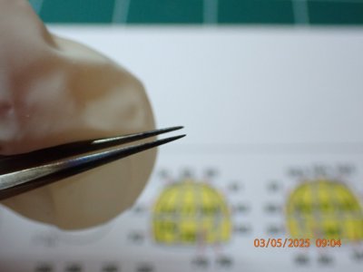
Sharp thin tweezers are essential as are the rubber gloves. These new ones are a little loose but the tight ones I bought last time made my hands sore. Compromises!
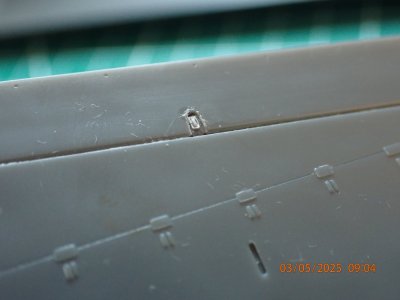
I broke off a control horn under the wing. This was not a surprise and I may well not bother replacing them (I removed the other one deliberately) because delicate underwing things always get broken by careless fingered people like me.
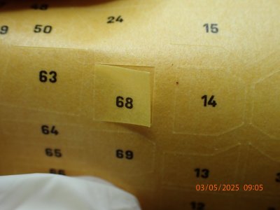
That's what pre-cut masks look like.
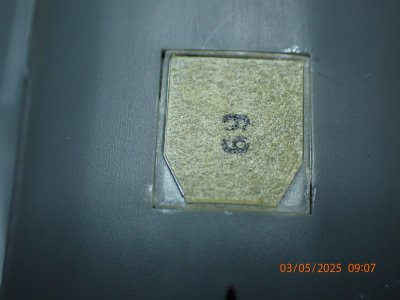
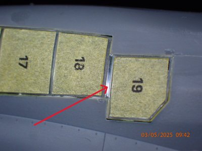
That's how good a fit they are. Note that the 0.1mm of shiny clear glass on the left is MY error, not Scale Mask's. My old eyes, even with magnifiers, no longer permit perfection. Say lavvy.
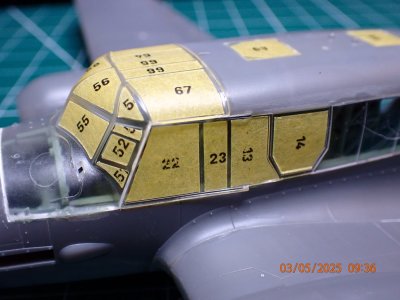
See how they are building up. I said there were lots of them.
I like the way Airfix moulded the windscreen integrally with the top of the nose. The join is a lot easier to make this way with no risk to the 'glass'.
That tiny window wasn't provided with a mask. I made one from the spare paper in the mask set and found out why. It's just too thin for this paper. I could have made a suitable mask from copper tape, the stuff we use on ship bottoms. I could have ... years ago, but not now.
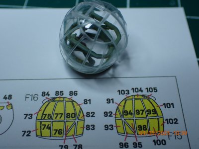
Did I mention that there are quite a lot of windows? The turret alone has 33 pieces of masking on the panes of perspex.
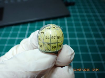
I saved this part until last because it was so much fun.

All done. Note the extra bits on the turret where the gun will be fitted. That's not covered by the pre-cuts, it's expected that you will sort things like that out for yourself. The blue liquid is latex masking fluid. You can buy latex very cheaply in big bottles but I prefer to pay the premium for the blue dye and neat little bottle that Vallejo provide for modellers.
A grand Saturday morning playtime!
Painting begins ... with preparation. First, I donned rubber gloves. I won't touch the model with my fingers again until it's completely finished.
I degreased the entire surface of the model with IPA (India Pale Ale? No, isopropyl alcohol). This was to get rid of the fingerprints that I will have left everywhere. I wiped the larger surfaces with a paper towel soaked in IPA and then went over the windows with a soaked cotton bud to give the window masks their best chance of sticking.
Next, I had to mask the windows, and there are a lot of them. I mentioned before that I'd bought a set of pre cut masks made by Scale Mask and they were brilliant. They fitted really well, were sticky enough to hang on through lots of painting and handling but not so sticky that removing them for repositioning became difficult. They were thin and flexible so they stretched over compound curves but stiff and strong enough for me to be able to reposition them without them stretching out of shape. They also made masking the Anson a two hour job, with a break in the middle because my eyes were bleeding, instead of a week if I'd been cutting my own masks from Tamiya tape.
I enjoyed the process too!!!

Sharp thin tweezers are essential as are the rubber gloves. These new ones are a little loose but the tight ones I bought last time made my hands sore. Compromises!

I broke off a control horn under the wing. This was not a surprise and I may well not bother replacing them (I removed the other one deliberately) because delicate underwing things always get broken by careless fingered people like me.

That's what pre-cut masks look like.

That's how good a fit they are. Note that the 0.1mm of shiny clear glass on the left is MY error, not Scale Mask's. My old eyes, even with magnifiers, no longer permit perfection. Say lavvy.

See how they are building up. I said there were lots of them.
I like the way Airfix moulded the windscreen integrally with the top of the nose. The join is a lot easier to make this way with no risk to the 'glass'.

That tiny window wasn't provided with a mask. I made one from the spare paper in the mask set and found out why. It's just too thin for this paper. I could have made a suitable mask from copper tape, the stuff we use on ship bottoms. I could have ... years ago, but not now.

Did I mention that there are quite a lot of windows? The turret alone has 33 pieces of masking on the panes of perspex.

I saved this part until last because it was so much fun.

All done. Note the extra bits on the turret where the gun will be fitted. That's not covered by the pre-cuts, it's expected that you will sort things like that out for yourself. The blue liquid is latex masking fluid. You can buy latex very cheaply in big bottles but I prefer to pay the premium for the blue dye and neat little bottle that Vallejo provide for modellers.
A grand Saturday morning playtime!
I wished I had known about those masking kits, what a clever idea.


