BALDER, Vlaardingen Herring Lugger from 1912, scratch build scale 1:50 Plate-On-Frame

Hi Peter,

I still have a lot of very fine foam, see below in the background of my fluyt. This is foam used for cnc milled tool case interiors.
If you want to test it I can put some of the in the mail, you can fill up the complete hold with it
View attachment 453192
Thanks for the offer, Maarten. I’ll keep it in mind if my idea does not work. You will see the result or I let you know to send a part.
Regards, Peter
 
Last edited:
The stone Jack Jager mentioned my be part of the answer?? event excessive weight, floating stone will be placed in the cargo holds between the cement.
Maybe the cement was floated on a bed of pumice which flexed?

There were ships actually made of concrete...see link. No flex and if they failed, it was catastrophic and immediate!! https://en.wikipedia.org/wiki/Concrete_ship
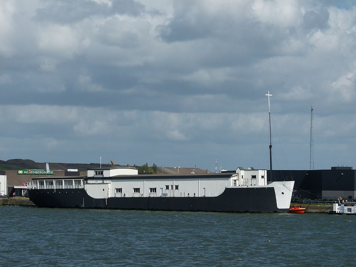
Thanks for the post and the wiki-link. When you open the Dutch version, you will found by the examples this:
Still floating in Antwerpen Belgium.
Interesting stuff.
Regards, Peter
 
I diluted some wood filler with water so that it could be applied with a brush and still flowed. Colored with some gray. Then covered all the foam pieces:
0273 Cement Vloer.jpg
Now looks more like a cement filling.
Remember that you do not see this view on the Balder itself. At most as a floor. It is not applied tightly there, such as the floor of your home.
I still have to touch up a few spots of paint, but I wanted to show you this 2nd attempt.

With a photo with reference:
0274 Referentie.jpg
Just to show you what we're talking about. The papillary lines on my thumb are almost as big as......... ;)
Regards, Peter
 
Nice solution. Much better this way.
This looks loads bette than the earlier "concrete", at least it looks more like concrete.
Yes sir, I believe you have captured the look of concrete.
Thanks guys. The outcome is indeed better. I'm not completely satisfied yet. I miss the ends of the plates of the wrangles between the keel and keelson, which I now have accentuated a little bit in the cement. But we will see what is possible.
Regards, Peter
 
Thanks guys. The outcome is indeed better. I'm not completely satisfied yet. I miss the ends of the plates of the wrangles between the keel and keelson, which I now have accentuated a little bit in the cement. But we will see what is possible.
Regards, Peter
Hello. And why not use natural cement without additives of high strength? Then you don't need to choose a color.
 
Hello. And why not use natural cement without additives of high strength? Then you don't need to choose a color.
Thanks for thinking with me, Anatoly. But I didn't have that at home. And the shopkeeper wouldn't open a package and sell me the amount of a teaspoon.;)
Seriously: I used the wood filler last week and thought it was a nice alternative.:)
Regards, Peter
 
The only thing, which you should or could consider is the surface of the concrete along the center line (green arrows)
Your model is representing a cut - means also the surface of the concrete should look like a cut through the concrete
The top (red arrow) is correct - this will be only leveled by a trowel

Screenshot 2024-06-14 104000.png

Here is a typical concrete cut - it has a complete smooth surface

Screenshot 2024-06-14 104814.png

Sorry - it is commenting on a model of highest standard - and maybe also because I am a civil engineer - so concrete is my daily business

We saw: "Mosern auf hohem Niveau" - like a eating in a 5* restaurant and saying, that the wine should be 0,5° colder
 
Thanks for thinking with me, Anatoly. But I didn't have that at home. And the shopkeeper wouldn't open a package and sell me the amount of a teaspoon.;)
Seriously: I used the wood filler last week and thought it was a nice alternative.:)
Regards, Peter
:) My house is under renovation, so cement in any quantity. That's why I thought about him.
 
You also thanks for thinking with me on this build, Uwe.
And thanks for the ‘5* restaurant’ comparison. :rolleyes:
About:
Your model is representing a cut - means also the surface of the concrete should look like a cut through the concrete
Thats the problem, it’s not cut but build in halves….. ;) Therefore it also would not be allowed by the HCSA ….. :(
This also makes the finish susceptible to differences of opinion.
PS-1:
Perhaps the HCSA will introduce the sub-membership of the HCBC: The Half-Cut Build Club. :) But then there must be a representative amount of builds.
PS-2:
Just a little difference: they used for the cementing only ‘the best cosson cement and sharp river sand’.
So no little stones in it (pebbles?).
Regards, Peter
 
Last edited:
Time for the actual construction of the inside:
0275 Kolen en Tonnen.jpg
The hold under the forecastle.
At the front is the storage of the coal for both stoves in the forecastle and the galley. That space is called 'Hell'.
With a wooden wall as a partition for the extra storage of barrels. Every bit of space was used.
Both areas are accessible through 3 hatches in the floor of the forecastle.
The stove in the forecastle is under the 'light' and in front of it is the hatch in the floor.
Between the stairs and the stove are the two hatches for the barrel hold.
Only empty barrels were stored there because they were brought up and down the steep stairs from the forecastle. Once filled they remained on deck.

I once again dived into my 'never throw away box' for the coal. I still had a bag of train roadbed stones:
0276 Kolen.jpg
Selected the smallest.
Then blackened with Schmincke Ink:
0277 Kolen.jpg
It dries just matt. Also sorted to size for assembly in the hold. The largest one at the back because you can't see it anyway.

First made and installed the wooden wall:
0278 Kolen.jpg
And start filling the hold with the coal.
With a slightly overexposed photo, otherwise you won't see the coals:
0279 Kolen.jpg
There is already a emptiness in the stock above left. So something has already been used by the crew.;)
Aren't the coals a bit big? It's not like it used to be at home with the smaller species. Rough men live here, the heating has to be done quickly. So 'large pieces, home quickly'. If a piece is too big, just hit it with a hammer or wooden shoe.:)
regards, Peter
 
The barrel hold.
First the floorboards. The old specifications speak of 1 1/2" pine slats. That must have been thumbs and that is why I use inches. That would be 0.76 mm in scale.
The slats I intended for this are on average 0.85 mm. Decided to take something off anyway.

I was considering purchasing the compact Proxxon DH40 thicknesser. But if it could handle the thin slats, I asked Maarten @Maarten. He has this one in use and I thought the Byrnes too. His advice was not to purchase the Proxoon because with the thin slats there is a very good chance that the knives would snap and the slats would break.
That saves another purchase of x euros. The Byrnes with sanding rollers could handle that.
Apart from the question of whether Byrnes still delivers, given Jim's death, that would be an even bigger investment.
That's why I was creative. The Proxxon BFW-40/E is a robust machine. I put a sanding roller in it and with the cross table I can set the distance very precisely.
0280 Sander.jpg
With the necessary guidance, the slats will go through just fine.

Then I started painting a number of barrels that I had previously had printed with the correct shape and dimensions.
These are stretched piece by piece in the Peroxxon DB250 lathe:
0281 Barrel.jpg
Colored by hand with a Talens Econine BrushPen. Since I used it on my BluenoseI really liked the use of Ecoline and Schmincke ink.

Then opted for black hoops:
0282 Barrel.jpg
The ink dries lighter. That's what I had in mind because herring barrels are made of an unprocessed light wood. Certainly not oak because that would affect the taste of the herring. Often also pine wood that is burned during bending. They then discolour on the outside under the influence of the salty seawater.

The floorboards 0.76 x 3.1 mm installed:
0283 Floor.jpg
The old specifications: 'The floors are made of 1 1/2" pine wood with non-connecting sides.....'. Water and dirt fall through and are drained to 2 pumps, further in the hold.
As well as 3 sparring battens of 1 mm along the retaining frames so that the barrels do not bang on the iron frames.
From the side this also gives a nice line division:
0283 Regels.jpg
Every viewing angle provides a surprising view of the interplay of lines. But then again, there won't be anything to see anymore.

A number of barrels placed in the hold:
0284 Barrels.jpg
It turns out that the dimensions of this hold are tailored to the floor planks and the height of the barrels.
Filled the hold a little further:
0285 Barrels.jpg
Filling it completely is of no use, as it is no longer visible after the forecastle floor has been installed. Except the part that provides a possible view with an open hatch in the floor.

With a picture of both parts together:
0286 2-delen.jpg
It gives you a different look on the added parts.

Now first make some construction blocks for support because the model will now gain quite a bit of weight. That will be a bit too much for the 2 pins on which the model currently stands.
Regards, Peter
 
Last edited:
Very good, that you have mentioned the hammer - I have no wooden shoes by hand ..... ;)
The coal is looking very realistic :cool:
 
Time for the more serious work: the forecastle.
The restoration book of the Maritime Museum contains a beautiful technical drawing of the layout of the forecastle:
0287 Vooronder tekening.jpg
(Source: Scheepvaartmuseum Restoration Book, page 90: "Crew quarters in the forecastle. Working drawing by S. de Jong.')

I have taken more than enough photos of the forecastle in the current Balder.
With a wide angle lens:
0288 Vooronder.jpg
From the corner next to the stairs, diagonally to the left towards the front.
So there are 2x6 bunks. Those of the captain and the helmsman are in the rear of the ship. They do have their own place to eat: on the left against the wall at the front with the partition in between. These 2 seats were called 'de Stee'.

Seen from 'de Stee' backwards:
0289 Vooronder.jpg
Next to the stairs is the passage to the galley. You can just see the bench that has a view to the stove and the handle of the water pump. That bench is against the wall of the drying hold on the port side.
The galley:
0290 Kombuis.jpg
Behind the stove it is the wall of the drying hold on the starboard side.

Made a mockup with a few copies of Sybe de Jong's drawing to scale and some cutting:
0291 Kooien.jpg
Numbers placed at the 6 bunks on the port side. Bunks 5 and 6 are positioned transversely, against the wall of the drying hold.
0292 Kooien.jpg
A is a narrow space behind B, 'de Stee'. Clothes can be hung against the wall.
C is the bench that runs along the bunks in a horseshoe shape.
The walls will support the deck beams, so that the temporary support in the middle is no longer necessary.

The planks on the outside, which are bead planks, become a challenge. Let's see if the AL's profile scrapers can make such a profile. Otherwise I have to sharpen one myself.
Another challenge: the stairs and the stove are in the middle, over the center profile. A new recess in my construction mold? The stove of the galley is located in the starboard side construction. Creative with nibbled walls.
Regards, Peter
 
Last edited:
Back
Top