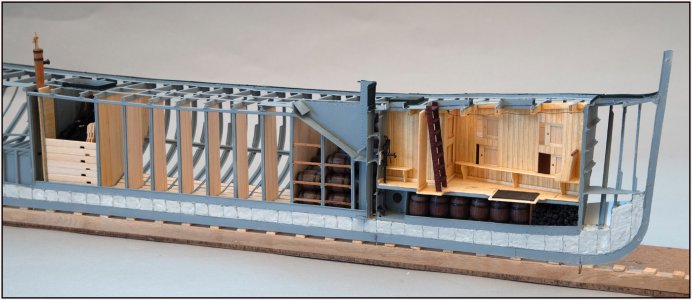
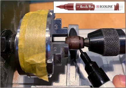
After my post last Tuesday (#1351) and the mention of the empty hold between wall 9 and the watertight bulkhead 10, there was a little voice in the back of my head that told me: something is not right here.
In such a lugger of limited dimensions, every bit of space is used. And somewhere I had also read something about that part on either side of the kossing.
So I started reading both restoration books again because the old drawings did not provide any answers.
With the result in the Amsterdam book on p. 24:
"The length of a tier hold (note: barrel hold) on the Balder was 800 to 850 mm internally, so that a barrel always fitted in there. The hatch opening was 760 mm long and 600 mm wide. The double tier hold (the first hold) had a length of 1520 mm. So two barrels could lie behind each other here. This was done so as not to weaken the connection of the ship at the location of the mast tube with an extra hatch opening in the deck."
I got to work on that by first removing that wall again. The planks were slid out of the profiles one by one. I can reuse them again.
I tried out with the help of some barrels whether the dimensions were correct:
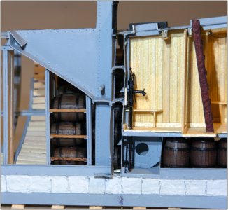
And immediately got to work to try out what I had in mind to prevent the barrels from rolling out of my model: The beams in the lengthwise direction between the U-profiles.
At the height of the 'belly' of each row of barrels, such a beam is placed. That beam rests on 2 small knees that are fitted in both U-profiles. I cut them from the 1.5 x 1.5 mm L-profile and are less than 1 mm thick. The beams are 1.15 x 0.9 mm.
Is that strong enough to hold such a row of barrels?
Remember that in the ship, the barrels are loaded on both sides and therefore roll against each other. In reality, there were bulkheads placed in the middle in the lengthwise direction. But then you can no longer see my barrels ........ A bit of FI .....
Here is the sketch of how the barrels were stacked and are positioned per row:
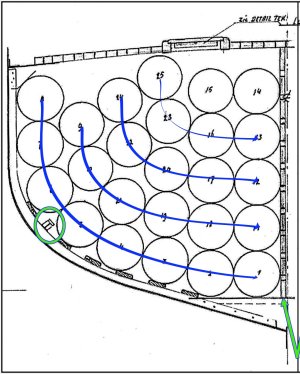
More reinforcement beams are drawn on the drawing. I do 1 per row. There are 5 beams in the other holds.
As you can see in de 1st picture under the sloping part of the kossing, 3 rows of barrels would have free space. The 4th one is already resting against the kossing. I left that out to keep a bit of a view inside.
And indeed: exactly 2 barrels fit in that hold one after the other.
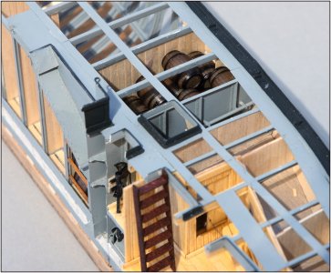
The dimensions of the old drawing are correct and did I build that correctly.
The front row rests against the metal part that supports the kossing and mast tube.
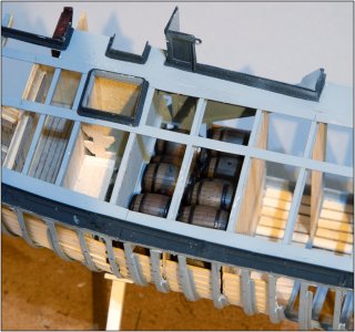
I don't think this is a Re-Do? It's an adjustment. That saves me a coin in the jar.
Regards, peter
In such a lugger of limited dimensions, every bit of space is used. And somewhere I had also read something about that part on either side of the kossing.
So I started reading both restoration books again because the old drawings did not provide any answers.
With the result in the Amsterdam book on p. 24:
"The length of a tier hold (note: barrel hold) on the Balder was 800 to 850 mm internally, so that a barrel always fitted in there. The hatch opening was 760 mm long and 600 mm wide. The double tier hold (the first hold) had a length of 1520 mm. So two barrels could lie behind each other here. This was done so as not to weaken the connection of the ship at the location of the mast tube with an extra hatch opening in the deck."
I got to work on that by first removing that wall again. The planks were slid out of the profiles one by one. I can reuse them again.
I tried out with the help of some barrels whether the dimensions were correct:

And immediately got to work to try out what I had in mind to prevent the barrels from rolling out of my model: The beams in the lengthwise direction between the U-profiles.
At the height of the 'belly' of each row of barrels, such a beam is placed. That beam rests on 2 small knees that are fitted in both U-profiles. I cut them from the 1.5 x 1.5 mm L-profile and are less than 1 mm thick. The beams are 1.15 x 0.9 mm.
Is that strong enough to hold such a row of barrels?
Remember that in the ship, the barrels are loaded on both sides and therefore roll against each other. In reality, there were bulkheads placed in the middle in the lengthwise direction. But then you can no longer see my barrels ........ A bit of FI .....
Here is the sketch of how the barrels were stacked and are positioned per row:

More reinforcement beams are drawn on the drawing. I do 1 per row. There are 5 beams in the other holds.
As you can see in de 1st picture under the sloping part of the kossing, 3 rows of barrels would have free space. The 4th one is already resting against the kossing. I left that out to keep a bit of a view inside.
And indeed: exactly 2 barrels fit in that hold one after the other.

The dimensions of the old drawing are correct and did I build that correctly.
The front row rests against the metal part that supports the kossing and mast tube.

I don't think this is a Re-Do? It's an adjustment. That saves me a coin in the jar.
Regards, peter
Last edited:


