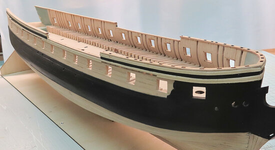
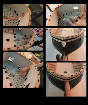
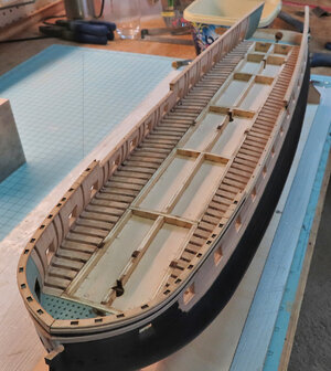
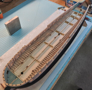
Belle Poule 1780 by Donnie

The scraper kit comes with the ship kit, or is sold separate, thanks
it comes as part of the kit.

Sorry @Donnie for off top
Scrapes from Atesania Latina can be bought separately see the example from Micro-Mark

 
Thank you Jim for answering this post. I must have overlooked it somehow. Yes,
The scraper / profiler / decorative tool does come w kit and the shapes are intended to be used on the model. However you can always keep the shaper for other projects.
 
it comes as part of the kit.

Sorry @Donnie for off top
Scrapes from Atesania Latina can be bought separately see the example from Micro-Mark

Jim, thanks, I will order a set!!
 
III. GUN DECK

This is the start of the Gun Deck and all associated components.

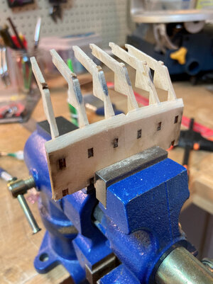
This is the Gun Deck Frame and is composed of 13 pieces. This frame will sit down into the upper hull between the ribs. This is not glued but only dry fit.

gundeck-01.jpg
 
NOTE: The Stern pieces can be difficult because there are many pieces that must all fit good and in unison. There are many angles and bevels. It is wise to dry fit parts often. Make sure the back stern plate (the part that has the windows cut out) fits well at the bottom of stern. You should not have any under or over hang.
There are those that are expert builders that would not have a problem, however for me and others probably with less experience might exhibit frustration with this part of the build.

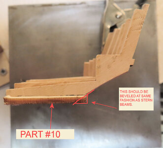
CORRECTION: PLEASE REFER TO LATER POST ABOUT THIS PART #10 AS THE "AFT" PART MUST BE BEVELED. MORE EXPLANATION IS GIVEN AT #233 POST.

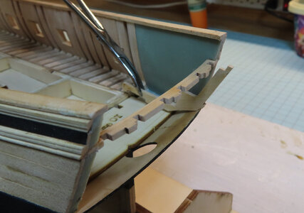
I am dry fitting the stern pieces here. There are other things to accomplish before installing these pieces. There is a stern decoration piece that I have soaked in hot water as it needs to be shaped into an arch.

However, this is where I am now.


This first picture is the last Deck Frame #10 as it lays flat and pushes into some tabs. The stern pieces will fit into the openings.

gundeck-06.jpg


These are dry-fitted only and will be removed as some more shaping is necessary.

gundeck-05.jpg


In stepping ahead one more step - the manual calls for the deck to be inserted onto the Deck Frame. The Deck is all one piece for now and this piece has to be bent very slightly to fit inside. I will remove this afterwards for now.

gundeck-04.jpg
 
Last edited:
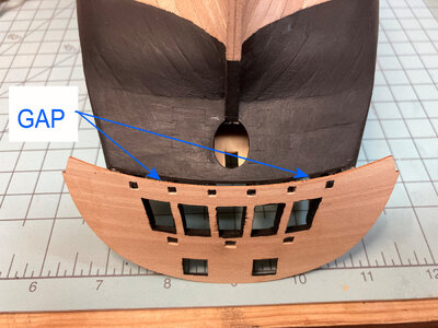
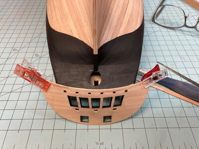
This next step has a part #14 beam that stretches from stern port to starboard. It is a small delicate piece. Before installing, make sure that the plastic stern pieces (or the GAP between the plastic stern pieces) are only wide enough to accept this horizontal stern reinforcement beam. If the stern backend is too wide, it will put too much stress on this piece and might cause it to break in half.
My stern was about 4 mm too wide and therefore, I used clamps to tighten the stern width. The clamp was set overnight and was sufficient that the stern plastic pieces held the shape so that the #14 beam would fit nicely without strain.
My apologies for the lack of correct nautical terms from here on.

CORRECTION: PART #10 MUST BE BEVELED - PLEASE SEE POST #233 FOR THE CORRECTION. THE COUNTER BEAMS AND PART #10 HAD TO BE REMOVED TO CREATE THE BEVEL. THIS BEVEL IS NECESSARY FOR THE LOWER STERN DECK TRANSOM TO HAVE THE SAME CURVE AS THE LOWER STERN SOLID PIECE.

gundeck-09.jpg


This shows obviously how to insert the frames into place and then gluing down.

gundeck-08.jpg


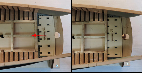
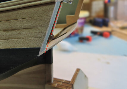
Next, the BASE of the plastic stern pieces and lower stern shroud piece needs to be filed so the main stern flat piece will fit flush.
You will see the RED LINE. This part of the frame should be FLUSH with the back plastic stern piece. The Frame has a positive notch or a "boss" tab. It needs to
protrude enough that it will fit into the main stern flat piece (the part that has the windows).

gundeck-07.jpg
 
Last edited:
ANOTHER MISTAKE -(small, but very significant)
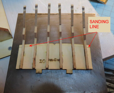
Part No. 10 MUST have a bevel to it - I have to remove part #10 - please stay tuned as I will be demonstrating with pictures.
 
Looking at part #10 and the way it is mounted with Stern Beams (lower counter timbers), you will see a SANDING LINE. It seems to me that this part should be flipped. For this reason, if you follow the SAND LINE as is, then the BEVEL will be facing the wrong way. However, for this situation, I will sand the bevel to FOLLOW the CURVE of the Stern Beams. (lower counter timbers).

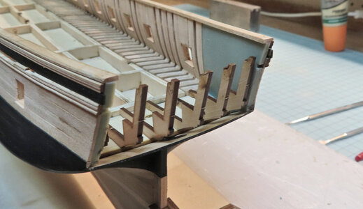
As you see, I removed part #10 with the lower counter timbers still glued.

gundeck-10.jpg


Next, I will sand the bevel in the direction shown. I hope that this is the correct procedure !!!

gundeck-11.jpg
 
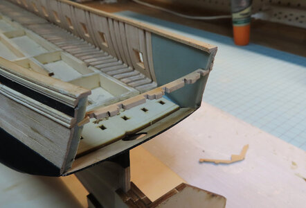
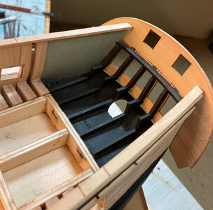
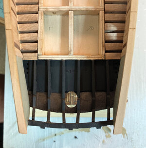
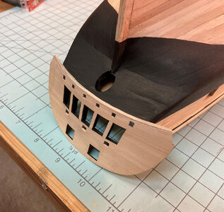
So, as it happens, the Captain got too much to drink and decided to paint the counter-frames black. We tried mutiny but it did not work. So we forced him to at least dry fit the Stern piece.

gundeck-13.jpg


gundeck-14.jpg
 
SANY0132.JPG

SANY0139.JPG

SANY0140.JPG
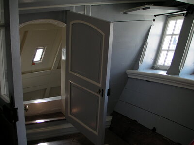
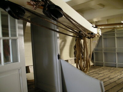
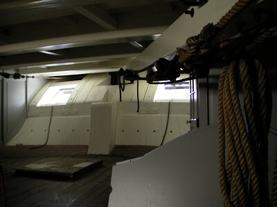
Photos Hermione, Rochefort. The cabin are painted in white or light gray. You can see nicely the counter timbers, the tiller and the inset windows.

Hi Donnie!

After a long vacation, i got new eye lenses and can see again like an eagle from 40 cm away to infinity. Unfortunately I can't read and model again until I get new reading glasses in a month. By your detailed construction report with the beautiful results I look forward to further model building.

Best regards
Thomas
 
Thank you again for all the likes and nice compliments. Moving onward to the finishing part of the stern - the mono piece (Stern "B") will have another mono piece glued on top so, the punch-out alignment openings will be covered up.

After installing this mono piece, I found that I had about a 1.5 mm gap.

This is something to watch out for - in my case, it was almost unavoidable. I hope that your build will be better. However, I was able to patch things up to make it better. This all will be covered up anyway.

gundeck-15.jpg

gundeck-16.jpg

gundeck-17.jpg
 
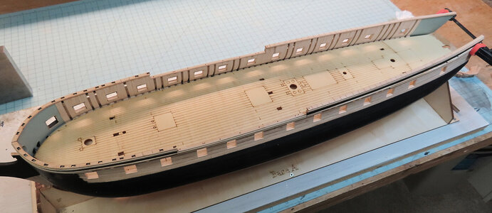
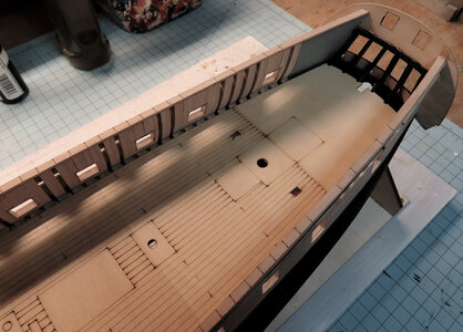
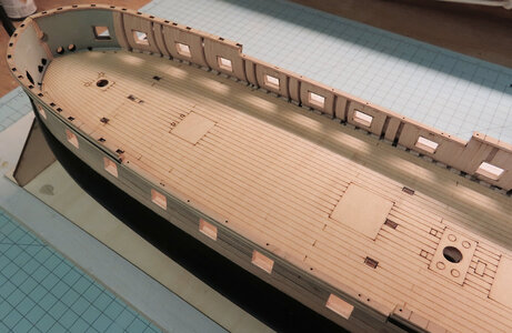
This set is after I installed the mono-piece deck piece. If you notice there is a gap along and around the entire piece next to the Bulwarks. The gap will be filled in with Sperketting and Waterways.

Also, as you probably guessed, this piece obviously covers all the "1/2 hull frames". I DID NOT use any glue on the hull frames, but only applied glue to the Deck Frame. I then weighed it down. There are positive alignment TABS on the Deck Frame that assist in the proper alignment of the mono deck structure piece.

gundeck-18.jpg

gundeck-19.jpg

gundeck-20.jpg

gundeck-21.jpg
 
Some missing diagrams / plans ?
So, the next step requires the 'Clamps' to be installed. The Clamps are in three strips which combined follow the entire length of ship from bow to stern. These Clamps will sit right above the Gun Ports. For those that might be unfamiliar with Clamps, they are Beams that run fore and aft entire length of ship along the inner side of the ship and they support all the Beams that are perpendicular to the Clamps.

So, in the manual at section 3-5, it calls for the "Clamp Location Drawings". The drawings are just templates to be placed inside the bulwarks to help determine the location of the Clamps (like a positioning guide).

Now, I have Drawings I, II, III, IV, and V. I also had a drawing that had the template for the Gun Ports. Back when I used those templates, I do not remember seeing any templates for the Clamp positioning.

Herein lies the problem. I can not find any such drawing or templates !!!

IF anyone else is building this model, I would appreciate some help and guidance on this. Yes, I know I can PM Sail & Sail, but not right now as the templates might be part of something else that I am not observing at the moment. I have reviewed all the other sheets that I have and can not find such a template.

In advanced reading of the manual several pages more, there are clues that I can use for the placement and it is possible to proceeed without the templates, but it still has me perplexed and I really wish I could figure this out. I am thinking that those templates did not come with kit. OR, what worries me is that those templates were ON the same sheet as the Gun Port templates - if that is the case, then those got thrown away as I cut out all the Gun Port Templates and threw the rest of the sheet away - I DO NOT remember seeing any other templates on that particular drawing !!!

Kindly
Donald
they were on the the same sheet with the gunport templates
 
Back
Top