-

Win a Free Custom Engraved Brass Coin!!!
As a way to introduce our brass coins to the community, we will raffle off a free coin during the month of August. Follow link ABOVE for instructions for entering.
-

PRE-ORDER SHIPS IN SCALE TODAY!
The beloved Ships in Scale Magazine is back and charting a new course for 2026!
Discover new skills, new techniques, and new inspirations in every issue.
NOTE THAT OUR FIRST ISSUE WILL BE JAN/FEB 2026
You are using an out of date browser. It may not display this or other websites correctly.
You should upgrade or use an alternative browser.
You should upgrade or use an alternative browser.
I sent you the files on google chatYes, zoltan, you are correct. I reviewed Jims review and saw it there. I do not know what I did with that sheet - not paying attention and I must have thrown that away.
View attachment 327892
Thank you Zoltan !!! It is greatly appreciated.
I need to be more careful and watchful. To others, I guess I had so much 'tunnel vision' - Its like looking for something on a table, and it is sitting right there in from of you, but for some reason, it falls in that 'blind spot' of your eyes.
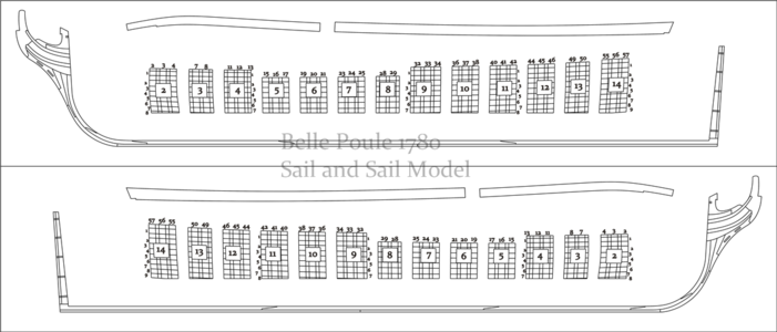
It would have been helpful if the templates would have been a darker OUTLINE and even labeled so as to make the templates stand out more.
This is dry fit only. I measured one of the Beams that will go into these slots. The slots will need slight filing to make the slot a little wider. It is much easier to do this now than to mount the Clamps and try to accomplishing this later. Even if the slot is to be made .2 mm wider, it will still make inserting the Beams easier. However, not all the Beams are the same width. If I remember looking at the plans, there are 3 different widths.
Therefore, there is a possibility that I might dry fit the entire structure on a bench before final glue up and installation. I will see later.
Therefore, there is a possibility that I might dry fit the entire structure on a bench before final glue up and installation. I will see later.
Donnie, I really appreciate the detail of your postings. I have just ordered the kit and will be studying your every move as I begin.
John
John
Hi John and thank you for following. There are a few 'Gotcha's', but most were my fault for not paying attention. What I like most about this kit is that the planking is actually preshaped. If you have any questions you can also PM me (start a conversation). There is a small 'envelope' icon to the right of your sign-in name. Click on the envelope and it will expand into a lower window of which you will then click on "start a new conversation". As soon as you start to type Donnie, (in the to: field) then my name should appear in the drop-down list. Then continue with the subject and text body.
Let me know when you get the box and I hope you start a Build Log !!!
Donnie
Let me know when you get the box and I hope you start a Build Log !!!
Donnie
Last edited:
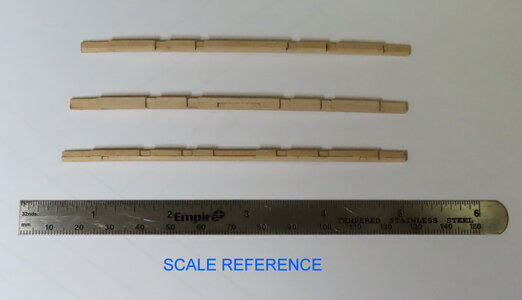
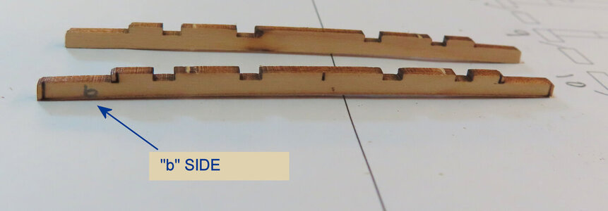
I have decided to build all the Deck Beams. I want to make sure they are going to fit in the Clamp before gluing the Clamp in. The Clamp notches can be filed out more if needed much easier than if it is installed. Here are Deck Beams 8, 9, and 10. Pay attention to the very small OFFSET notch on Beam #10.
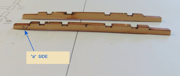
So far, the Beams are comprised of two parts (a & b). The "a" side faces the bow and "b" sides faces the stern.
-------------------------------------------------------------------------------------------------------------------
NOTE: please refer to this post for important info about the A and B sides.
-------------------------------------------------------------------------------------------------------------------
The first image is for scale reference only.
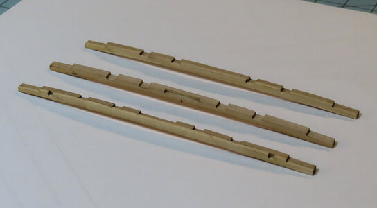
Pay attention to special offset notches on each side of Beam #10
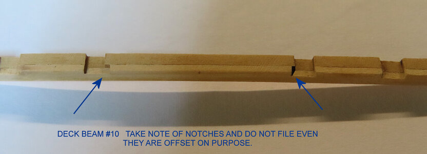
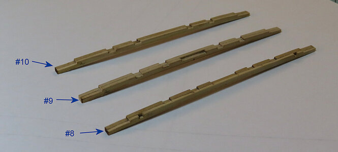
So far, the Beams are comprised of two parts (a & b). The "a" side faces the bow and "b" sides faces the stern.
-------------------------------------------------------------------------------------------------------------------
NOTE: please refer to this post for important info about the A and B sides.
Belle Poule 1780 by Donnie
Yes, zoltan, you are correct. I reviewed Jims review and saw it there. I do not know what I did with that sheet - not paying attention and I must have thrown that away.
shipsofscale.com
The first image is for scale reference only.


Pay attention to special offset notches on each side of Beam #10


Last edited:
Donnie,These are the last of the photos of the Hull Section. The last operation was to make the Bowsprit opening.
View attachment 326812
View attachment 326813
Did you take any pictures while cutting the bow sprit hole? Any detailing explanation would be enlightening.
Respectfully,
John
Post #227 is the only images I took. I started out with a pin vise and then continue with exacto and a round file until I got the opening like I wanted it.
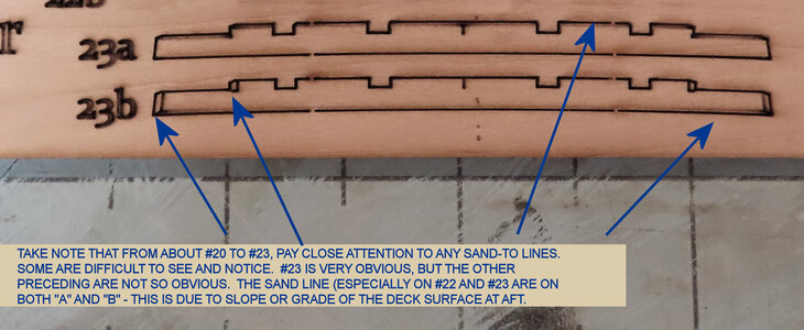
My apologies for the ALL caps. I was just wanting to copy and paste from the graphic. A little lazy here.
TAKE NOTE THAT FROM ABOUT #20 TO #23, PAY CLOSE ATTENTION TO ANY "SAND-TO" LINES. SOME ARE DIFFICULT TO SEE AND NOTICE. #23 IS VERY OBVIOUS, BUT THE OTHER PRECEDING ARE NOT SO OBVIOUS. THE SAND LINE (ESPECIALLY ON #22 AND #23 IS ON BOTH "A" AND "B" - THIS IS DUE TO THE SLOPE OR GRADE OF THE DECK SURFACE AT AFT.
My final approach and trajectory here is that I wish to fit the upper beams to make sure the clamp (notches) fit well with the Beams. It would be a hardship to widen the "notches" or "slots" on the Clamps after they are glued to the Bulwarks. Just MHO.
Now that I am finished with the Deck Beams, it is now time to dry fit the beams to the clamps on the bench first.

Thank you . . .Post #227 is the only images I took. I started out with a pin vise and then continue with exacto and a round file until I got the opening like I wanted it.
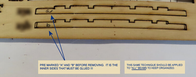
I should have mentioned this in a post a long time ago, but it is important to go ahead and mention it. If you look at parts A and B, you will see that I always LABEL those parts BEFORE I remove them. That is because the LABELED parts will face OUTWARD and the non--label will face inward. This will be very important as you get to parts very near the stern and bow due to special filing and sanding requirements (sanding lines). ALL "a" sides will face the BOW. ALL "b" sides will face the stern. Always compare to the plans.
-----------------------------------------------------------------------------
Now, I have finally dry-fitted all the Deck Beams. All the notches did have to be filed a little wider. However, some of this width could have been compensated for by sanding down each SIDE of the beams (this of course would also have the same effect.
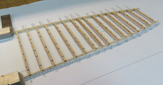
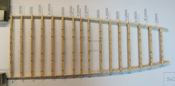


All parts will be removed and Clamps can be installed now. The Beams will be saved and put away unitil needed much further later in the manual.
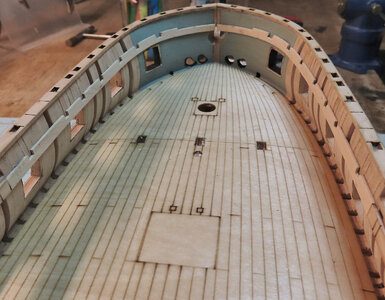
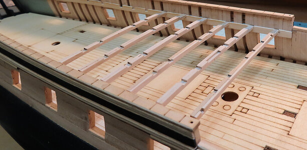
The aft (from Midship to Stern) clamps are installed and I am also working on gluing in the Fore Clamps (from midship to Bow). The Beams are NOT ready to install but will be at a much later time in the manual. Much to do before that time comes. However, I wanted to test fit some Beams to see how it goes so far and they seem to fit well. (I will now remove the Beams and put them away for that later time.

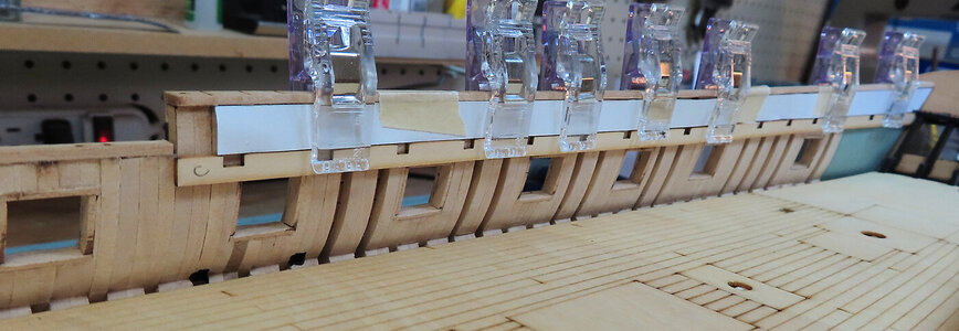
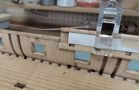
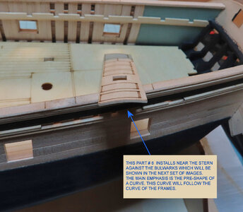
Installation of Part #6. Please pay attention to this part. I pre-bent the part (curve) to closely match the curve of the frames. It would be easier to clamp this part down - the curve does not have to be perfect, but is better than trying to glue a FLAT piece to a CURVED frame !!!
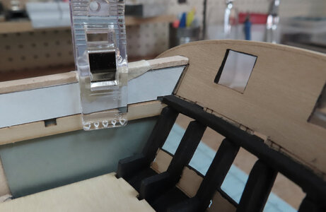
The next image shows that it is VERY important to follow a "DIVIDING LINE" near the Stern as this is where the END of Part # 6 terminates. Make sure that you push Part #6 all the way to the inside Stern to accommodate the correct positioning.
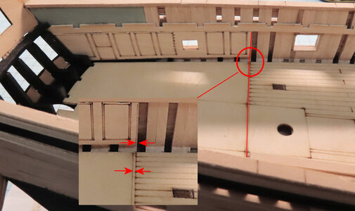
The next image shows that it is VERY important to follow a "DIVIDING LINE" near the Stern as this is where the END of Part # 6 terminates. Make sure that you push Part #6 all the way to the inside Stern to accommodate the correct positioning.


As I am installing planks inboard, it is now time to stop that process and focus on cutting out the Gun Ports. I like doing this before all Spirketting is installed. It's just easier (for me) to fit an Exacto knife to cut out - however, I guess another possibility is to go ahead with all the planks, then come back with a drill and make several holes and work the port out that way. Either way works.


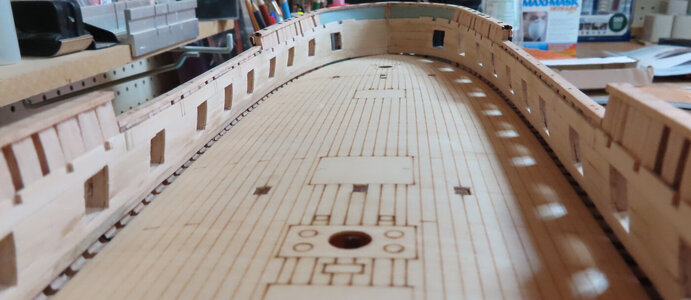
My apologies as this is not a good photo of interior Bulwarks. This just shows that all the Bulwark planking is done. I miss my other camera that gives a great depth of field - the point-and-shoot types are little to be desired in this manner.
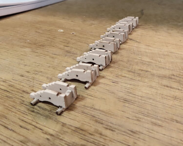
The next photo shows the start of the Cannons. Later, I will show in detail my build sequence on this. For now, note the larger hole about mid way of the side of the carriage - according to research, (for French ships) the Breeching line went through these holes. I will discuss this more later - please stay tuned for more info. Also as well, the eyebolts or ringbolts are installed in quite a different manner as well. The kit comes with PE parts that are VERY TINY.
The next photo shows the start of the Cannons. Later, I will show in detail my build sequence on this. For now, note the larger hole about mid way of the side of the carriage - according to research, (for French ships) the Breeching line went through these holes. I will discuss this more later - please stay tuned for more info. Also as well, the eyebolts or ringbolts are installed in quite a different manner as well. The kit comes with PE parts that are VERY TINY.
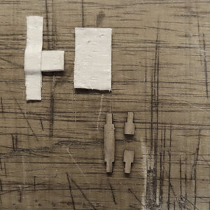
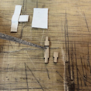
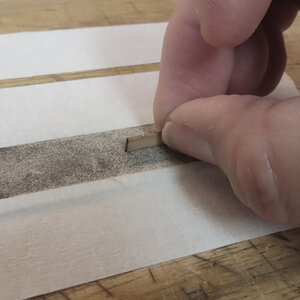
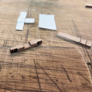
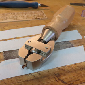
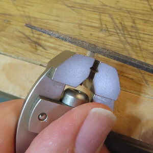
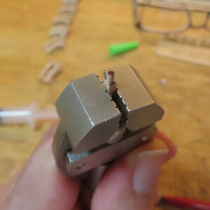
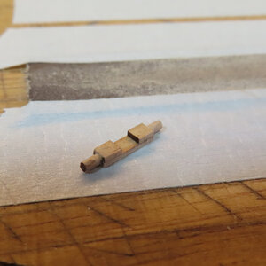
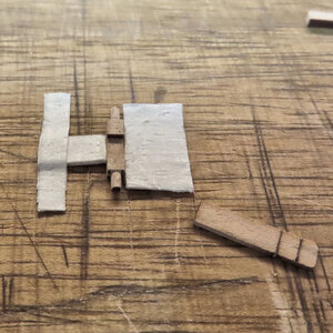
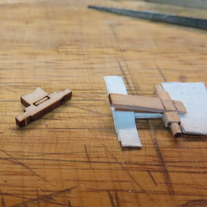
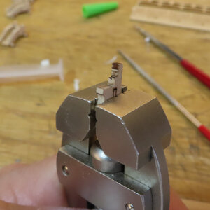
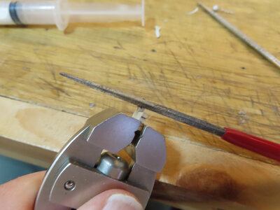
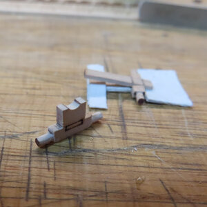
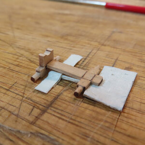
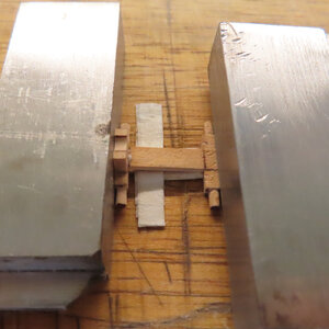
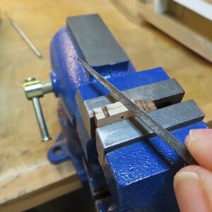
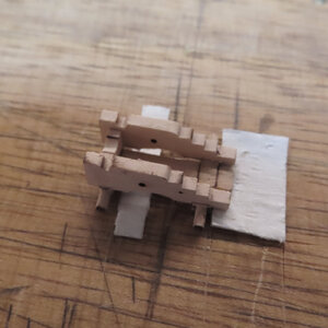
Here is the best of my ability to show a sequence of construction of carriages. The tool to help hold parts is from www.micromark.com here: https://micromark.com/Super-Hand-Vise
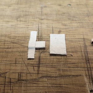
The white tape is just a very simple jig with several layers to "build up" a makeshift jig. I did not feel like going through the time of making a legitimate jig of wood or metal, etc.
The white tape is just a very simple jig with several layers to "build up" a makeshift jig. I did not feel like going through the time of making a legitimate jig of wood or metal, etc.


