-

Win a Free Custom Engraved Brass Coin!!!
As a way to introduce our brass coins to the community, we will raffle off a free coin during the month of August. Follow link ABOVE for instructions for entering.
-

PRE-ORDER SHIPS IN SCALE TODAY!
The beloved Ships in Scale Magazine is back and charting a new course for 2026!
Discover new skills, new techniques, and new inspirations in every issue.
NOTE THAT OUR FIRST ISSUE WILL BE JAN/FEB 2026
You are using an out of date browser. It may not display this or other websites correctly.
You should upgrade or use an alternative browser.
You should upgrade or use an alternative browser.
EDIT: Friends, it seems that I am getting worse about figuring things out for myself. After I went back and re-read this post, I am TOTALLY embarrassed - I am thinking of just deleting this post !!!
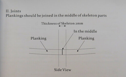
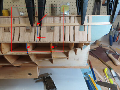
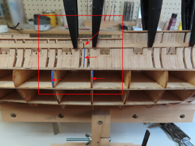
I am laying down my first plank #2a, 2b, and 2c. Now, the manual says that the PLANK JOINTS (BUTTS) are supposed to meet OVER the middle of the skeleton part (which is actually the Bulkheads.
Well, at least NOT SO for #2a, 2b, and 2c as you can see the joints of these parts are way off and the closest joint is actually very close to the REAL frame.
So, I do not understand. I can only assume that when the lower planks start to cover the lower bulkheads that it will be THOSE planks that will line up with that.
What to do? The planks here can not be modified to suit the bulkhead alignments - that clearly will not work - so therefore, I will just NUDGE (1mm) of the plank to line up with the real frame joints as shown. (the TOP two arrows)


Last edited:
Hi Donnie!
I think this is how it is correct. The gun deck has so many frames that it almost doesn't matter where the planks meet. In the lower part of the hull it will fit as shown in the drawing.
A nice neat job!
With warm regards
Thomas
I think this is how it is correct. The gun deck has so many frames that it almost doesn't matter where the planks meet. In the lower part of the hull it will fit as shown in the drawing.
A nice neat job!
With warm regards
Thomas
Thomas, I am sure that you are correct. I will continue with project - thank you very much for your encouragement.
At my office work - I am highly technical as being a Radio Engineer and one of my jobs is not only CAD drawings but also some technical manuals too. It is very important to be as step by step as possible with clear instructions so I do have a tendency to be taking everything literal - I need to pick back up with my logical skills -
Now, the manual for the Poole is nice (actually very nice), but it seems that a detail that is really needed is somehow left out for you to figure out on your own. I also used to read the plans and instructions way ahead to see about any problems I might encounter - I do not do that anymore, but, I need to get back into that habit again.
Now, the manual for the Poole is nice (actually very nice), but it seems that a detail that is really needed is somehow left out for you to figure out on your own. I also used to read the plans and instructions way ahead to see about any problems I might encounter - I do not do that anymore, but, I need to get back into that habit again.
Also, after reviewing Zoltans' build----- Thomas and Zoltan (of course) are correct. I feel quite dumb at the moment.
Just keep in mind, that the bulkheads of the POB-part of the model were not existing at the real ships.
So butt joints and also later on tree-nails have to be every time over "real" frames (or minimum filling timbers)
So butt joints and also later on tree-nails have to be every time over "real" frames (or minimum filling timbers)
Kurt Konrath
Kurt Konrath
Looking like your making nice progress on the planking.
It's your ship so who is to say your doing it wrong, your just doing it different, time will tell if its better or worst way to do it.
It's your ship so who is to say your doing it wrong, your just doing it different, time will tell if its better or worst way to do it.
You're making nice progress Donnie! And so beautifully done as well!
Thank you all - too kind !
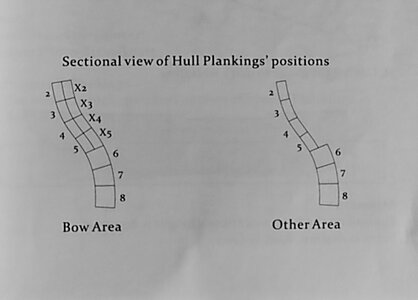
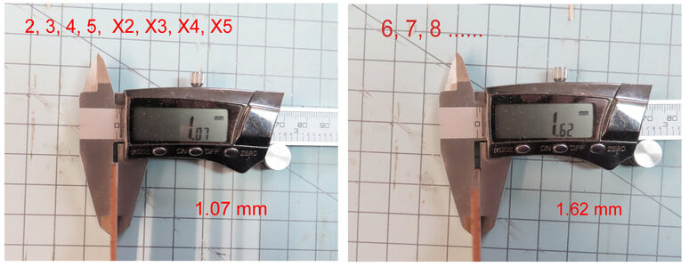
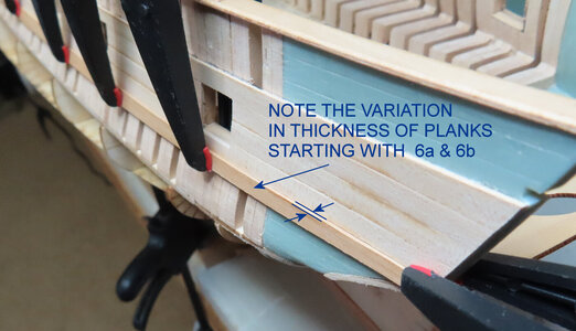
Well, before I move on to the next 6a, 6b, and so forth, I will do the other side of the ship. Now, it is very important to realize at this point that the REMAINDER of the planks is THICKER. So, it is a good idea to sand planks 2 - 5 as you DO NOT want to sand (2-5) and then sand (6 - ...) as you DO NOT want them to blend in at the same level.
I show a graphic of the different thicknesses of the boards and also a graphic from the manual for such.
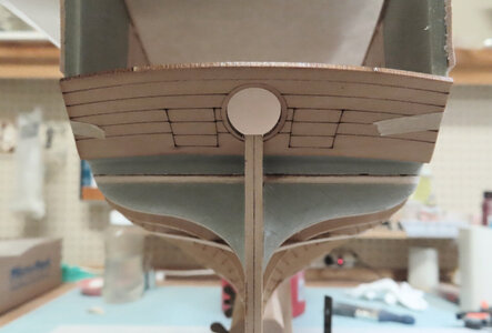
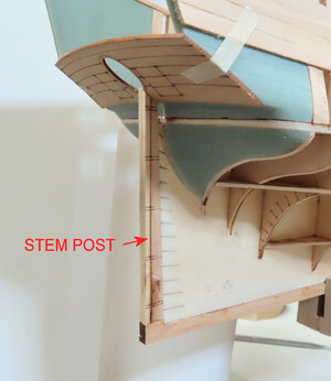
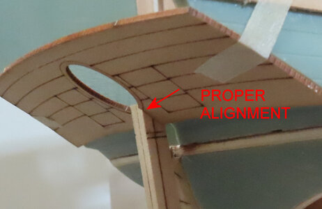
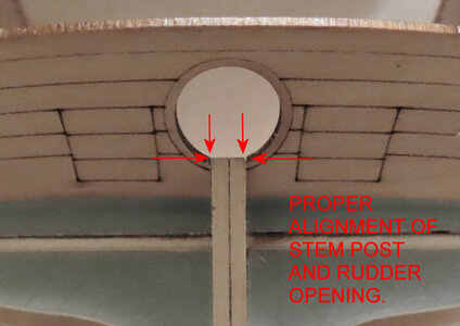
Good morning Donnie- outstanding work and great instructive log. Cheers GrantThe manual is now skipping to the installation of a stern part. In order to do this, it is necessary to go ahead and install the Stem Post - as really this offers a "guide" as to how to mount the stern piece.
View attachment 309295
View attachment 309296
View attachment 309297
View attachment 309298
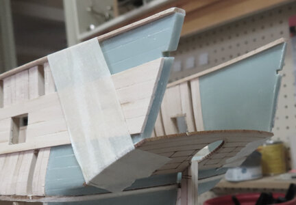
Now I am gluing up the stern piece and using masking tape to keep things in order while it dries.
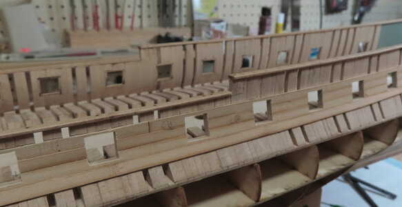
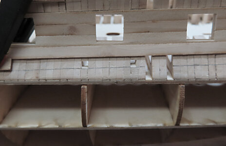
Next, the manual now calls for the Planking Strips to continue. There are some tiny portholes (perhaps scuppers) that will be cut out and that depends on if you wish to go through the trouble to do this. I plan to cut mine out and perhaps all the way through the hull. I will see. I will use a mill to drill tiny hole and then file out the square.
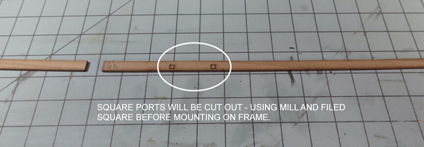
Next, the manual now calls for the Planking Strips to continue. There are some tiny portholes (perhaps scuppers) that will be cut out and that depends on if you wish to go through the trouble to do this. I plan to cut mine out and perhaps all the way through the hull. I will see. I will use a mill to drill tiny hole and then file out the square.

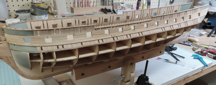
A continuation of the Planking sequence. Planks 6a and 6b and going forth are thicker than the first set. I DID NOT bevel the top edge as I wanted to make sure there is a defined edge between the two different thicknesses. It is easy to get carried away and so not sand too much and ruin the effect of the plank differences in thicknesses.
The purpose here is to show how I am cutting out the square openings (scuppers) and then filing them later.
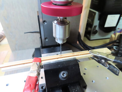
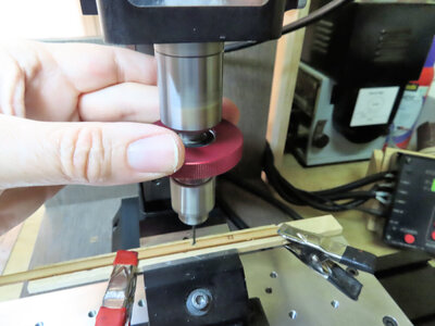
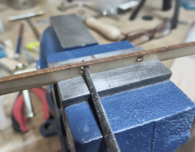
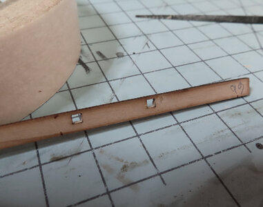
Demonstrating Sherline's Metric Mill with Sensitive Drilling Attachment (www.sherline.com)
The purpose here is to show how I am cutting out the square openings (scuppers) and then filing them later.


Demonstrating Sherline's Metric Mill with Sensitive Drilling Attachment (www.sherline.com)
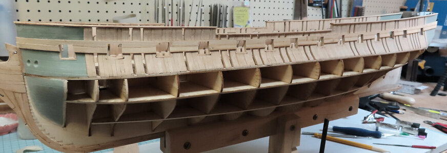
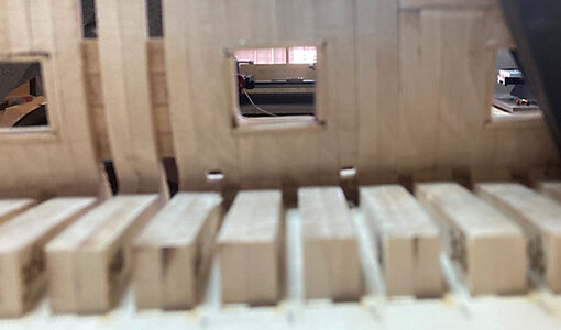
I marked off the location of the two scuppers on the frame and decided to drill and square file them out. The inboard photo is horrible. The scuppers from the inboard might be covered up with the waterways - not sure how it is going to turn out - but I will see - if it is covered up by all the inboard waterways, deck planking, then I am not worried about it - as at least, the outside appearance is done.
This camera I am using - for some reason just does not take photos like it used to - the lens is clean - not sure, it is about 2 years old and was bought for the sole purpose of ship build logs. It is a Canon SX740HS about $399 USD

This camera I am using - for some reason just does not take photos like it used to - the lens is clean - not sure, it is about 2 years old and was bought for the sole purpose of ship build logs. It is a Canon SX740HS about $399 USD

So far:
The Hawse holes are VERY tricky to drill / file out - be careful as the angle is slightly downward and at a strange angle. Do not try to drill straight in as you will drill into the Plastic Bow Pieces.
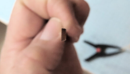
The edge image shows the typical beveling of a plank.
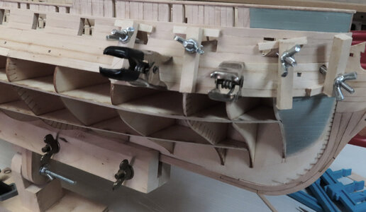
Typical Clamping - I cannot use the long nose clamps as they will not reach anymore. Back to my homemade clamps.
The Hawse holes are VERY tricky to drill / file out - be careful as the angle is slightly downward and at a strange angle. Do not try to drill straight in as you will drill into the Plastic Bow Pieces.
The edge image shows the typical beveling of a plank.

Typical Clamping - I cannot use the long nose clamps as they will not reach anymore. Back to my homemade clamps.


