HMS Victory - Caldercraft-Jotika - 1/72. Build log

Joined
Aug 15, 2019
Messages
360
Points
323

Location
Crackenback, NSW, Australia
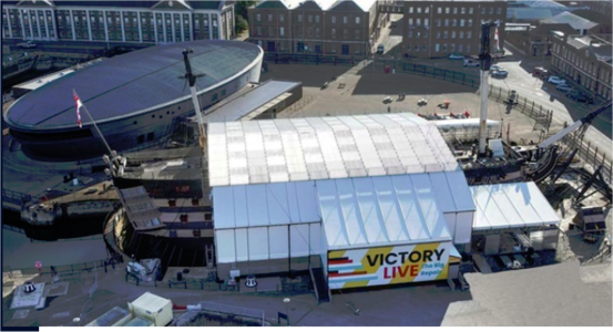
The time has come to embark on my NEW build - The HMS Victory using the POF wood kit of Caldercraft (Jotika). As most would know, HMS Victory remains one of the most 'modelled' of all model ships. Like the ship Vasa, it exists today, can be physically touched/seen and examined (albeit currently undergoing a MAJOR restoration at Portsmouth with an estimated £45m price tag - Refer to the Royal Navy site here).
1702271445054.png

One of the other benefits of having the physical ship existing is that there is a plethora of research material, books, plans and people available to ask questions, not only here at SOS but also the British Royal Navy Conservation foundation where a detailed Conservation Log is being provided - A bit like a Build Log only applicable to the REAL ship!!).

My Build Log here commenced as a gift I received while completing my Vasa model about half way through the 'Covid years' from The Admiral. With transition from work to retirement, plus the Covid lockdowns and also maintaining a working farm (in the reaches of the Snowy Mountains of southeast New South Wales, Australia), my time was limited to commence the build, but things have cleared a little now and I have some time, so the start has begun. As is my habit, I like to approach things carefully and so with a bit of research, and after a few searches of this forum (SOS), I noticed that although there are MANY entries and Build Logs for the Victory, strangely, there are actually not many describing the Caldercraft 1/72 wooden kit on Ships of Scale. To illustrate this, on the recently provided Index of Wooden Ships, there are 124 Victory build entries (or similar). Of these 124, there are SEVEN which I can find that are specifically related to the Caldercraft Kit and of these only 5 are actual Build Logs!!

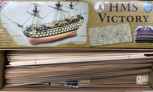
One of these by Hoss6262, exceptionally describes the entire kit, its 15 kg of enclosed material and all the exceptionally well prepared cut-out sheets etc. This is an expensive kit, but you pay for what you get. The quality is excellent, the parts fit together with very tight tolerances (and in some cases, too tight, as I will explain) and I have no complaint about the professionalism in preparing this kit. Even registration of the kit with the manufacturers, Jotika, brings benefits if parts require replacement or updating.
1702273086626.png
One of the other Build Logs (plus a comprehensive set of Youtube videos) has been provided by Paul1958 (a fellow Aussie!!) and this has proved to be exceptionally useful. I will not attempt to emulate Paul's excellent work, but on the way through the build, I will refer to his work, but also add a number of observations and comments of my own which might assist following builders.

So to start. I commenced by substantially modifying my 'workshop dry dock' after the Vasa build, to accommodate this bigger build and larger ship (both in scale and overall size). One of the things I did was change around the build area which meant I had the luxury of TWO desks with a 1.0 metre gap in the middle with a swivel chair, and the 'build desk', being an extended kitchen bench top that was considerably longer than the model, but which also allowed me to access the ship on BOTH sides. However as an added advantage (and one I found exceptionally useful with the Vasa build), was the use of a baseboard with keel clamps (similar to Paul1858's dock), but mounted on a large 'Lazy Susan'. A Lazy Susan is a circular, roller bearing mounted 'plate' which can be easily and cheaply purchased (Google 'Lazy Susan'). A Lazy Susan is a turntable (rotating tray) placed on a table or countertop to aid in distributing food, but in our case, provides the ability to simply rotate our baseboard-mounted ship which can then be rotated easily around the vertical axis.

A little unconventionally, but a good place to start, I wanted to eventually mount the Victory on a baseboard for display. The Manual describes the use of three 1/8" brass rods, drilled into the central keel area where brass rods can be inserted to mount the finished ship. I wanted something a little more sturdy, and so in the keel, I drilled three holes but then mounted three cross-threaded round push-through nuts (as obtained and used from Ikea furniture), and these then allowed me to insert thin screws (size M5), and actually bolt down the ship once mounted.
1702274279890.png
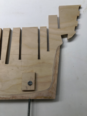
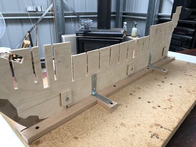
I reinforced these nuts with additional 5mm ply (making sure their placement did not interfere with the bulkheads on either side, and this allows a VERY rigid and firm securing of the model along its keel. Note in the photo above too, I have already chamfered the base ends of the keel as described on Plan 2 of the kit. This MUST be done early in the build, and I recommend it be done BEFORE placing any bulkheads as it means you are working on a flat surface to sand and Dremel machine off the required chamfer. I ALSO recommend that you LEAVE OFF the stern walnut keel extension and base keel at this time. The stern walnut will be applied later when the planking is completed to make a neat and clean finish, but the base keel stern walnut piece can be left until just before first planking. So, the mounted centre keel/spine is as shown below. Note the three mounting nuts, plus the bracket supports (as used by Paul1958 in his first Youtube video).
IMG_1501.JPG

The NEXT stage is the placement of the bulkheads. I will leave this to the next build log entry.

Regards,

PeterG

Expended hours: 32 hours.
 
Last edited:
Oooh! This is exciting! I'm happy that you have now found some time to commence this build Peter and look forward to seeing your progress. As you know I'm a big fan of your work having benefited from your example on the Vasa. I'd still be trying to sort the rigging if you hadn't shared your belay chart... Anyway, best of luck and enjoy the build!
 
Great .... I will follow with big interest
 
Initially, MANY THANKS to the many who have visited this new build log.
I am hoping there is enough popcorn and chairs to go around!!!

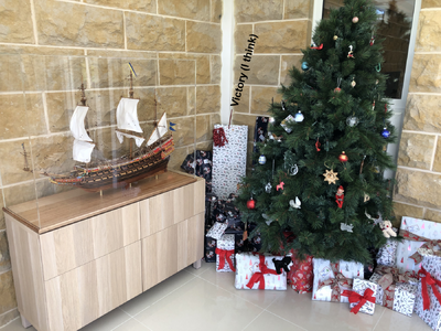
In particular, Paul (dockattner), we go back a long way and I appreciate your comments regarding the rigging and our Vasa builds. I am watching your Kingfisher build with interest too. It is another work of art, rather than a shipmodelling exercise. Maltbyguy too, yes it will be a challenge, and the space required to display a ship of this size presents its own challenges. Fortunately, I live on a farm with a large Conservatory, and we have a couple of spaces to spare in there. In my previous build with the Vasa, the finished model was mounted to a baseboard and a large plexiglass case purpose-built for the display. In the picture below, being Christmas (Happy Christmas everyone), the corner will be the right place for the Victory - (not sure about where the Christmas tree will go). There might be some negotiations to be had with The Admiral!!

1702418427798.png

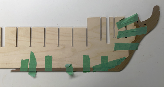
Something I should have mentioned earlier (when I spoke about the walnut keel pieces (there are four)), which are fixed to the base of the 5mm plywood keel, is that, when gluing these to ensure a tight seam between the walnut and the plywood, the keel pieces were taped. This ensured a tight fit and the CNC cut was so accurate that it did not even require clamps to ensure a seamless joint. (Note in the below picture, I have only glued the front and forward keel section). As described previously too, before fixing the walnut keel, I chamfered the 5mm plywood to the shape (as detailed in Plan 2 - see Paul1958 in his first Youtube video) although this is not as shown in the photo below (I rethought this and chamfered BEFORE gluing the walnut). This chamfering of the 5mm plywood, brings it down to 3mm. The first planking then adds a further 2mm (both sides of 1mm planks) to bring it back to 5mm, After the fist planking it will again require sanding/chamfering down to 3mm so the second planking arrives at 5mm again and is the correct thickness to add the walnut keel and aft walnut section with a neat, butted joint for the planking to keel (this is why the rear keel and rear stern pieces of walnut are left off at this stage.

1702419423388.png

Now, the Victory bulkheads - Following along from Paul1958's example and as per the Manual, I started to loose fit the bulkheads to the centre keel. There are 18 individual bulkheads, beautifully clean with CNC cuts and no laser burn marks (very appreciated). The individual bulkheads have 3 connecting points to the outer support scarf for each of six 5mm plywood sheets. This kit is of such high quality, that even each connection point is slightly deepened so that when a knife blade (I use a Stanley Utility knife), is used to cut out the joints, they come away easily with a firm push of the blade. A simple rub with some sandpaper then cleans the connection point cleanly.

So with each of the 18 numbered bulkheads (numbering is VITALLY IMPORTANT once detached from their individual sheets) I loose fitted Bulkhead 9 (middle of the ship). Well here is where the trouble started. These CNC cuts are SO precise and tight, it took me 5 minutes to engage the upper cut (of the bulkhead and the lower cut of the receiving keel/spine). The fit was VERY tight and it took a LOT of my weight pushing down to get the bulkhead correctly fitted. Well, I thought, "I have 17 others of these to go - are they all going to be this tight?" I then moved to Bulkhead 4 and without pushing it down, it too was clearly going to be VERY tight. So, going back to Bulkhead 9, I attempted to pull it free from the loose fit (no glue) of the keel/plywood joint. After an hour of trying, I eventually managed to separate the bulkhead from the keel, but with a VERY high risk of damage. Clearly either the humidity was too high, something had shrunk or grown, not sure, but I couldn't possibly fit all 18 bulkheads without doing damage or worse, breaking the keel section, even though it was 5mm plywood. So, I really had no choice but to enlarge the two cuts in the bulkhead, and its adjoining keel cut slot locations. To do this, I judiciously used my fine circular bench table saw and took about 0.25mm off each bulkhead and keel slot. Obviously, I tested the fits as I went and even so, the fit was very tight. After doing ALL 18 bulkheads and keel slots, I was ready to move on.

IMG_1503.JPG

Two more problems arose as I started to place the bulkheads onto the keel slots.

1. In the picture above, you can see the glue, and in some cases, a small amount had 'dribbled' down to the mounting timbers I had used on each side of the keel. I soon realised that if I just left it there and moved on, in the end, the keel would be firmly glued to the mount timber. So, I added strips of masking tape (green) to prevent the glue attaching to the base timbers. This worked fine, despite my attempts to wipe away and limit the glue finding its way to the bottom.

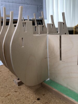
2. The second issue I found was that as I pushed the bulkheads down, I reached a point where I could not see the 'gap' between the bottoms of the slots in each bulkhead and keel slots. This meant I wasn't sure if I had seated the bulkhead all the way home to close the slots. This had to be done to millimetre accuracy, so close-enough wasn't good enough!! The workaround I came up with was to draw a thin pencil line on BOTH the bulkhead and keel slots where the slots ended. So, when inserting the bulkhead onto the keel (and having to hit it down with a piece of wood and a small rubber mallet, the fits were still that tight!!), the TWO LINES came together and the bulkhead was correctly seated (see picture above).

The next stage is to fit the 5mm plywood lower gun decking. Virtually none of this deck is seen from the upper finished model, so there is no requirement for it to be planked. It's purpose is for hull strength and to ensure all bulkheads are aligned and strongly supported. I fitted this with little difficulty and glued it in to place. At this stage with the bulkheads/keel/lower deck glued and rigid, I thought while everything was open, I would test fit the three masts. This proved a valuable thing to do as the fit was not possible without some filing of the lower slots in the keel section which provide the mast footings when fitted. The alignment with the hole in the deck was correct, but the slots needed either reducing the mast diameters, or enlarging the keel slots. I did this to the keel slots with the Dremel and a sanding wheel, but this could NOT be done internally once the ship was closed up. The picture below gives you an example using the foremast. You can clearly see the amount I would have had to sand down and reduce the diameter of the foremast base to obtain a good fit into the mast slot. So far as I could tell, there was no distortion or bending of the keel or surrounding slots - It was just a really tight fit.

IMG_1504.JPG

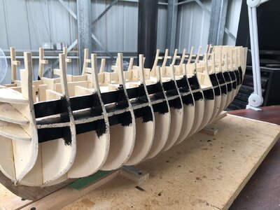
Insertion of the four dummy gun backings was no problem and these fitted simply by chamfering the fronts slightly then tapping them through the 17 bulkheads (Bulkhead 1 at this stage is not glued in place as this needs additional pieces added later (pieces 20 and 21). Once glued in place, I cut out the gap between bulkheads 9 and 10 (as this is the ships entryway on both sides), and painted the gun enclosures black (more on this later) for the lower and orlop gun decks.

IMG_1509.JPG

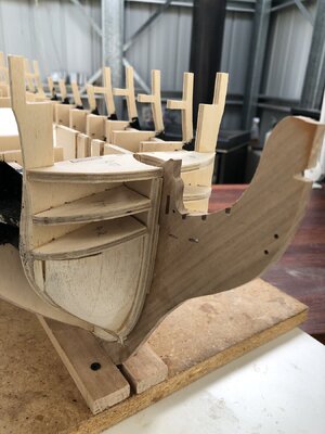
Sanding of the forward and aft bulkheads to allow for the bending of the first planking was also done at this stage. There is a lot of judicious sanding, some Dremel usage, and lots of using a 'test' strip of planking to get the angles right to allow the correct bulkhead edge angles to ensure the correct planking curvature. You can see these angles in the picture above. Also note in this picture that I have added Bulkhead 1 and the additional forward supports as the Manual and Plans describe.

From previous experience with the Vasa and the tight 'folding' of the forward planking around the tight bow curve, I thought I would also like some extra support for this first plank fitting. So, I fashioned two balsa blocks to fit in the forward opening and sanded them to provide extra support. This is shown below:

IMG_1511.JPG

This about completes the hull construction for the skeleton of the ship. My next task, while the ship is open, is to consider additional embellishments that I would like to add. One thing I have found with my Vasa, that has tremendous appeal, is that I added internal hull lighting. This 'wows' people when they see it at night, and so I thought I would attempt this again with the Victory. This will be the content of my next post.

Regards,

PeterG

Elapsed time: 64 hours
 
Last edited:
Initially, MANY THANKS to the many who have visited this new build log.
I am hoping there is enough popcorn and chairs to go around!!!

In particular, Paul (dockattner), we go back a long way and I appreciate your comments regarding the rigging and our Vasa builds. I am watching your Kingfisher build with interest too. It is another work of art, rather than a shipmodelling exercise. Maltbyguy too, yes it will be a challenge, and the space required to display a ship of this size presents its own challenges. Fortunately, I live on a farm with a large Conservatory, and we have a couple of spaces to spare in there. In my previous build with the Vasa, the finished model was mounted to a baseboard and a large plexiglass case purpose-built for the display. In the picture below, being Christmas (Happy Christmas everyone), the corner will be the right place for the Victory - (not sure about where the Christmas tree will go). There might be some negotiations to be had with The Admiral!!

View attachment 413668

Something I should have mentioned earlier (when I spoke about the walnut keel pieces (there are four)), which are fixed to the base of the 5mm plywood keel, is that, when gluing these to ensure a tight seam between the walnut and the plywood, the keel pieces were taped. This ensured a tight fit and the CNC cut was so accurate that it did not even require clamps to ensure a seamless joint. (Note in the below picture, I have only glued the front and forward keel section). As described previously too, before fixing the walnut keel, I chamfered the 5mm plywood to the shape (as detailed in Plan 2 - see Paul1958 in his first Youtube video) although this is not as shown in the photo below (I rethought this and chamfered BEFORE gluing the walnut). This chamfering of the 5mm plywood, brings it down to 3mm. The first planking then adds a further 2mm (both sides of 1mm planks) to bring it back to 5mm, After the fist planking it will again require sanding/chamfering down to 3mm so the second planking arrives at 5mm again and is the correct thickness to add the walnut keel and aft walnut section with a neat, butted joint for the planking to keel (this is why the rear keel and rear stern pieces of walnut are left off at this stage.

View attachment 413670

Now, the Victory bulkheads - Following along from Paul1958's example and as per the Manual, I started to loose fit the bulkheads to the centre keel. There are 18 individual bulkheads, beautifully clean with CNC cuts and no laser burn marks (very appreciated). The individual bulkheads have 3 connecting points to the outer support scarf for each of six 5mm plywood sheets. This kit is of such high quality, that even each connection point is slightly deepened so that when a knife blade (I use a Stanley Utility knife), is used to cut out the joints, they come away easily with a firm push of the blade. A simple rub with some sandpaper then cleans the connection point cleanly.

So with each of the 18 numbered bulkheads (numbering is VITALLY IMPORTANT once detached from their individual sheets) I loose fitted Bulkhead 9 (middle of the ship). Well here is where the trouble started. These CNC cuts are SO precise and tight, it took me 5 minutes to engage the upper cut (of the bulkhead and the lower cut of the receiving keel/spine). The fit was VERY tight and it took a LOT of my weight pushing down to get the bulkhead correctly fitted. Well, I thought, "I have 17 others of these to go - are they all going to be this tight?" I then moved to Bulkhead 4 and without pushing it down, it too was clearly going to be VERY tight. So, going back to Bulkhead 9, I attempted to pull it free from the loose fit (no glue) of the keel/plywood joint. After an hour of trying, I eventually managed to separate the bulkhead from the keel, but with a VERY high risk of damage. Clearly either the humidity was too high, something had shrunk or grown, not sure, but I couldn't possibly fit all 18 bulkheads without doing damage or worse, breaking the keel section, even though it was 5mm plywood. So, I really had no choice but to enlarge the two cuts in the bulkhead, and its adjoining keel cut slot locations. To do this, I judiciously used my fine circular bench table saw and took about 0.25mm off each bulkhead and keel slot. Obviously, I tested the fits as I went and even so, the fit was very tight. After doing ALL 18 bulkheads and keel slots, I was ready to move on.

View attachment 413671

Two more problems arose as I started to place the bulkheads onto the keel slots.

1. In the picture above, you can see the glue, and in some cases, a small amount had 'dribbled' down to the mounting timbers I had used on each side of the keel. I soon realised that if I just left it there and moved on, in the end, the keel would be firmly glued to the mount timber. So, I added strips of masking tape (green) to prevent the glue attaching to the base timbers. This worked fine, despite my attempts to wipe away and limit the glue finding its way to the bottom.

2. The second issue I found was that as I pushed the bulkheads down, I reached a point where I could not see the 'gap' between the bottoms of the slots in each bulkhead and keel slots. This meant I wasn't sure if I had seated the bulkhead all the way home to close the slots. This had to be done to millimetre accuracy, so close-enough wasn't good enough!! The workaround I came up with was to draw a thin pencil line on BOTH the bulkhead and keel slots where the slots ended. So, when inserting the bulkhead onto the keel (and having to hit it down with a piece of wood and a small rubber mallet, the fits were still that tight!!), the TWO LINES came together and the bulkhead was correctly seated (see picture above).

The next stage is to fit the 5mm plywood lower gun decking. Virtually none of this deck is seen from the upper finished model, so there is no requirement for it to be planked. It's purpose is for hull strength and to ensure all bulkheads are aligned and strongly supported. I fitted this with little difficulty and glued it in to place. At this stage with the bulkheads/keel/lower deck glued and rigid, I thought while everything was open, I would test fit the three masts. This proved a valuable thing to do as the fit was not possible without some filing of the lower slots in the keel section which provide the mast footings when fitted. The alignment with the hole in the deck was correct, but the slots needed either reducing the mast diameters, or enlarging the keel slots. I did this to the keel slots with the Dremel and a sanding wheel, but this could NOT be done internally once the ship was closed up. The picture below gives you an example using the foremast. You can clearly see the amount I would have had to sand down and reduce the diameter of the foremast base to obtain a good fit into the mast slot. So far as I could tell, there was no distortion or bending of the keel or surrounding slots - It was just a really tight fit.

View attachment 413673

Insertion of the four dummy gun backings was no problem and these fitted simply by chamfering the fronts slightly then tapping them through the 17 bulkheads (Bulkhead 1 at this stage is not glued in place as this needs additional pieces added later (pieces 20 and 21). Once glued in place, I cut out the gap between bulkheads 9 and 10 (as this is the ships entryway on both sides), and painted the gun enclosures black (more on this later) for the lower and orlop gun decks.

View attachment 413674

Sanding of the forward and aft bulkheads to allow for the bending of the first planking was also done at this stage. There is a lot of judicious sanding, some Dremel usage, and lots of using a 'test' strip of planking to get the angles right to allow the correct bulkhead edge angles to ensure the correct planking curvature. You can see these angles in the picture above. Also note in this picture that I have added Bulkhead 1 and the additional forward supports as the Manual and Plans describe.

From previous experience with the Vasa and the tight 'folding' of the forward planking around the tight bow curve, I thought I would also like some extra support for this first plank fitting. So, I fashioned two balsa blocks to fit in the forward opening and sanded them to provide extra support. This is shown below:

View attachment 413675

This about completes the hull construction for the skeleton of the ship. My next task, while the ship is open, is to consider additional embellishments that I would like to add. One thing I have found with my Vasa, that has tremendous appeal, is that I added internal hull lighting. This 'wows' people when they see it at night, and so I thought I would attempt this again with the Victory. This will be the content of my next post.

Regards,

PeterG

Elapsed time: 64 hours
Congrats on a great start to this fantastic kit. Adding lighting will make it really spectacular. I am 13 months into my build on this kit and am building up the fore and main masts now. I found the kit to be exceptionally high quality, material plentiful, and the help provided by Paul Vickers' videos to be very helpful. An obvious admonition is to read the instructions, read them again, and read ahead a page or two as you progress. I found virtually all the needed info to be somewhere in the instructions/plans, sometimes I found needed info a step late:(
Really looking forward to your build/progress.
 
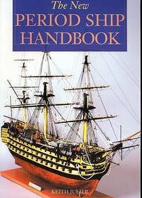
Thank you Paul (dockattner) and Adiefenbach. I would love to see some pictures of your build Adiefenbach - It sounds intriguing. You are also correct with reading the Manual plus importantly, reading a few pages in advance. I have also found the book (and I have a few on Victory), which is "The New Period Ship Handbook". This gives step-by-step build comments but from a builder's perspective and following along with the kit Manual for the Victory but also a range of other ships such as the Endeavour, The Bounty and Agamemnon. (amongst others).

1702507976223.jpeg

Now I was wanting to introduce some lighting within the hull of the ship, and this could really only effectively be done while the hull was unplanked. As we move higher, access is a little easier as it can be installed sequentially before upper decks go on (and so hide the wiring). I was keen to have a 'period' source for the lighting and with a little research on Google, it now turns out that for very cheap cost, you can buy online, yellow/white FLICKERING LEDs which for my purpose look like candles/wick lanterns when their light brightens and dims randomly. Turns out they were only a few cents each and when wired on to a 'test breadboard', gave an excellent light.

LED BACKGROUND

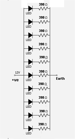
A little bit of knowledge and background is required to wire up LEDs, but anyone can do it. The LED is a light device which is a diode and therefore passes current only one way. Hence a positive and negative (cathode and anode) rule has to be applied when connecting to a power source. The LEDs I was using were rated at 3 Volt and 25 milliAmps (or 0.025 Amps). LEDs are also a 'current' device, so that once their 3V threshold is provided, they will light up, and then draw current to illuminate. An excess of voltage beyond 3 volts however (and this must be DIRECT CURRENT, and I chose a 12 volt power source), will overload the LEDs and cause them to burn out. Therefore to limit the voltage going to the LEDs, a resistance is required to reduce the voltage to the correct value. This resistance can be calculated by the formula:

Resistance (ohms) = (Vs - Vf) / LED forward current (Amps) where Vs is the source voltage 12v) and the Vf is the LED rated voltage (3V), so for my example,

= (12 - 3) / 0.025 = 360 ohms. The safest nearest standard resistor value is 390 ohms.

There are also a wide range of LED Resistance Calculators which can do the sum for you (for example, here).

Also, LEDs can be wired in series or parallel. In the case of wiring the hull, it is a simple matter to run two wires the length of each side of the ship (which act as 'bus' connections for parallel wiring of the LEDs). These wires can be near the cannon bays, then by drilling two holes at the back of the cannon bay, the LED can be inserted, and the two wires soldered to the POSITIVE wire (including a 390 ohm resistor), and then the anode of the LED connected to the NEGATIVE wire such that polarity is provided. This parallel wiring allows for a LOT of LEDs to be connected to the 'bus' wiring running through the hull. The power source gets a connection at the stern of the ship and then can be extended to lie outside the ship with 'hidden' wiring to the main supply transformer (delivering 12 volt DC with rated 2.5 Amp current), which should be sufficient for up to about 60 LEDs. The diagram below gives you an idea of the circuit with the two vertical lines on the left and right side acting as the 'bus' wires duplicated around each inside of the hull.

1702614585614.png

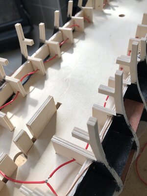
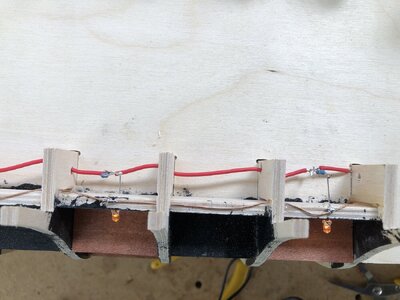
In the circuit above, I have shown 10 LEDs but this can be extended to many more. Below is a picture of the hull with the Lower Deck in place and you can see the RED (positive) bus which weaves in and out of the bulkheads down the length of both sides of the ship.

IMG_1513.JPG

Also running down the inside on top of the dummy cannon wall is a bare copper wire to act as the earth or NEGATIVE bus. I have left this wire bare as it makes the soldering in tight spaces easier. The next picture shows the resistors and LEDs in place and the second picture with four LEDs connected and operating.

IMG_1521.JPGIMG_1522.JPG

I have experimented here to test whether I prefer the LED to be mounted horizontally or vertically. I think the vertical mounting is better, as it more subtly displays the light and it looks more like an internal lamp/lantern hanging from the deck above. Note too, that I have added in a thin flat base of stained balsa. This looks better to me than the black, but I also do not think I will place LEDs at EVERY cannon bay - only a select few (say 7-8 along each deck level).

After wiring up for the middle deck, and testing, I placed the outer plywood patterns with the gun ports in place for the middle and lower gun decks (using pins and clamps). Hmmmm, here is where I met a quandary. With the extra lighting inside and highlighting the internal cannon bays, I am now going to have to add additional internal details. The lighting allows a view internally that people are definately going to look in to. For example, the lower two cannon decks use 'dummy' cannons and these look very obvious with the LED lights inside. Similarly, the floors will need to appear to have planking in the cannon bays. The floors are not a problem as its simple to glue some correctly cut and planked bases. The cannons are however an issue, as I am going to have to construct some 'false' cannon trucks, which from the outside will appear 'real'. This will take some time and will have to be done for about 60 dummy cannons on the lower and middle decks!! On decks above this, cannon trucks are part of the kit yet to be constructed.

If I just construct some balsa vertical truck sides and a base of the right proportions (no wheels or ropes etc), I think I can get away with it. I will play around and see how I go.

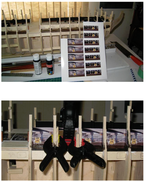
I came across one other builder (robipod who is on MSW), who has dealt with the above internal view problem quite differently. He has gone to the extent of using Victory internal photos and with CorelDraw, fashioned individual cannon bay inserts using photographic paper, then sticking these around the internal walls of each cannon bay - A very interesting idea (see photos below - With full appreciation and thanks to robipod for using his method). Definately food for thought.

1702616582198.png

Regards,

PeterG

Elapsed Time = 92 hours
 
... I have also found the book (and I have a few on Victory), which is "The New Period Ship Handbook". This gives step-by-step build comments but from a builder's perspective and following along with the kit Manual for the Victory but also a range of other ships such as the Endeavour, The Bounty and Agamemnon. (amongst others).
For everybody interested


and also the other handbooks by Keith Julier

 
The time has come to embark on my NEW build - The HMS Victory using the POF wood kit of Caldercraft (Jotika). As most would know, HMS Victory remains one of the most 'modelled' of all model ships. Like the ship Vasa, it exists today, can be physically touched/seen and examined (albeit currently undergoing a MAJOR restoration at Portsmouth with an estimated £45m price tag - Refer to the Royal Navy site here).

View attachment 413224

One of the other benefits of having the physical ship existing is that there is a plethora of research material, books, plans and people available to ask questions, not only here at SOS but also the British Royal Navy Conservation foundation where a detailed Conservation Log is being provided - A bit like a Build Log only applicable to the REAL ship!!).

My Build Log here commenced as a gift I received while completing my Vasa model about half way through the 'Covid years' from The Admiral. With transition from work to retirement, plus the Covid lockdowns and also maintaining a working farm (in the reaches of the Snowy Mountains of southeast New South Wales, Australia), my time was limited to commence the build, but things have cleared a little now and I have some time, so the start has begun. As is my habit, I like to approach things carefully and so with a bit of research, and after a few searches of this forum (SOS), I noticed that although there are MANY entries and Build Logs for the Victory, strangely, there are actually not many describing the Caldercraft 1/72 wooden kit on Ships of Scale. To illustrate this, on the recently provided Index of Wooden Ships, there are 124 Victory build entries (or similar). Of these 124, there are SEVEN which I can find that are specifically related to the Caldercraft Kit and of these only 5 are actual Build Logs!!

One of these by Hoss6262, exceptionally describes the entire kit, its 15 kg of enclosed material and all the exceptionally well prepared cut-out sheets etc. This is an expensive kit, but you pay for what you get. The quality is excellent, the parts fit together with very tight tolerances (and in some cases, too tight, as I will explain) and I have no complaint about the professionalism in preparing this kit. Even registration of the kit with the manufacturers, Jotika, brings benefits if parts require replacement or updating.

View attachment 413225
One of the other Build Logs (plus a comprehensive set of Youtube videos) has been provided by Paul1958 (a fellow Aussie!!) and this has proved to be exceptionally useful. I will not attempt to emulate Paul's excellent work, but on the way through the build, I will refer to his work, but also add a number of observations and comments of my own which might assist following builders.

So to start. I commenced by substantially modifying my 'workshop dry dock' after the Vasa build, to accommodate this bigger build and larger ship (both in scale and overall size). One of the things I did was change around the build area which meant I had the luxury of TWO desks with a 1.0 metre gap in the middle with a swivel chair, and the 'build desk', being an extended kitchen bench top that was considerably longer than the model, but which also allowed me to access the ship on BOTH sides. However as an added advantage (and one I found exceptionally useful with the Vasa build), was the use of a baseboard with keel clamps (similar to Paul1858's dock), but mounted on a large 'Lazy Susan'. A Lazy Susan is a circular, roller bearing mounted 'plate' which can be easily and cheaply purchased (Google 'Lazy Susan'). A Lazy Susan is a turntable (rotating tray) placed on a table or countertop to aid in distributing food, but in our case, provides the ability to simply rotate our baseboard-mounted ship which can then be rotated easily around the vertical axis.

A little unconventionally, but a good place to start, I wanted to eventually mount the Victory on a baseboard for display. The Manual describes the use of three 1/8" brass rods, drilled into the central keel area where brass rods can be inserted to mount the finished ship. I wanted something a little more sturdy, and so in the keel, I drilled three holes but then mounted three cross-threaded round push-through nuts (as obtained and used from Ikea furniture), and these then allowed me to insert thin screws (size M5), and actually bolt down the ship once mounted.

View attachment 413226
I reinforced these nuts with additional 5mm ply (making sure their placement did not interfere with the bulkheads on either side, and this allows a VERY rigid and firm securing of the model along its keel. Note in the photo above too, I have already chamfered the base ends of the keel as described on Plan 2 of the kit. This MUST be done early in the build, and I recommend it be done BEFORE placing any bulkheads as it means you are working on a flat surface to sand and Dremel machine off the required chamfer. I ALSO recommend that you LEAVE OFF the stern walnut keel extension and base keel at this time. The stern walnut will be applied later when the planking is completed to make a neat and clean finish, but the base keel stern walnut piece can be left until just before first planking. So, the mounted centre keel/spine is as shown below. Note the three mounting nuts, plus the bracket supports (as used by Paul1958 in his first Youtube video).

View attachment 413227

The NEXT stage is the placement of the bulkheads. I will leave this to the next build log entry.

Regards,

PeterG

Expended hours: 32 hours.
Hi Peter
Very detailed build log
I'll definitely follow your build with great interest
Adding internal lights is excellent.
 
Last edited:
I'm very happy to see you start your HMS Victory Peter. I truly appreciate your approach. It is clear you have invested time in planning the project and I'm confident the results will reflect that! With so many accomplished builders on SoS I'm running out of time to read all the progress and still work on my own ship. ROTF But I will not miss out on your journey! You're off to a super start.
 
The time has come to embark on my NEW build - The HMS Victory using the POF wood kit of Caldercraft (Jotika). As most would know, HMS Victory remains one of the most 'modelled' of all model ships. Like the ship Vasa, it exists today, can be physically touched/seen and examined (albeit currently undergoing a MAJOR restoration at Portsmouth with an estimated £45m price tag - Refer to the Royal Navy site here).

View attachment 413224

One of the other benefits of having the physical ship existing is that there is a plethora of research material, books, plans and people available to ask questions, not only here at SOS but also the British Royal Navy Conservation foundation where a detailed Conservation Log is being provided - A bit like a Build Log only applicable to the REAL ship!!).

My Build Log here commenced as a gift I received while completing my Vasa model about half way through the 'Covid years' from The Admiral. With transition from work to retirement, plus the Covid lockdowns and also maintaining a working farm (in the reaches of the Snowy Mountains of southeast New South Wales, Australia), my time was limited to commence the build, but things have cleared a little now and I have some time, so the start has begun. As is my habit, I like to approach things carefully and so with a bit of research, and after a few searches of this forum (SOS), I noticed that although there are MANY entries and Build Logs for the Victory, strangely, there are actually not many describing the Caldercraft 1/72 wooden kit on Ships of Scale. To illustrate this, on the recently provided Index of Wooden Ships, there are 124 Victory build entries (or similar). Of these 124, there are SEVEN which I can find that are specifically related to the Caldercraft Kit and of these only 5 are actual Build Logs!!

One of these by Hoss6262, exceptionally describes the entire kit, its 15 kg of enclosed material and all the exceptionally well prepared cut-out sheets etc. This is an expensive kit, but you pay for what you get. The quality is excellent, the parts fit together with very tight tolerances (and in some cases, too tight, as I will explain) and I have no complaint about the professionalism in preparing this kit. Even registration of the kit with the manufacturers, Jotika, brings benefits if parts require replacement or updating.

View attachment 413225
One of the other Build Logs (plus a comprehensive set of Youtube videos) has been provided by Paul1958 (a fellow Aussie!!) and this has proved to be exceptionally useful. I will not attempt to emulate Paul's excellent work, but on the way through the build, I will refer to his work, but also add a number of observations and comments of my own which might assist following builders.

So to start. I commenced by substantially modifying my 'workshop dry dock' after the Vasa build, to accommodate this bigger build and larger ship (both in scale and overall size). One of the things I did was change around the build area which meant I had the luxury of TWO desks with a 1.0 metre gap in the middle with a swivel chair, and the 'build desk', being an extended kitchen bench top that was considerably longer than the model, but which also allowed me to access the ship on BOTH sides. However as an added advantage (and one I found exceptionally useful with the Vasa build), was the use of a baseboard with keel clamps (similar to Paul1858's dock), but mounted on a large 'Lazy Susan'. A Lazy Susan is a circular, roller bearing mounted 'plate' which can be easily and cheaply purchased (Google 'Lazy Susan'). A Lazy Susan is a turntable (rotating tray) placed on a table or countertop to aid in distributing food, but in our case, provides the ability to simply rotate our baseboard-mounted ship which can then be rotated easily around the vertical axis.

A little unconventionally, but a good place to start, I wanted to eventually mount the Victory on a baseboard for display. The Manual describes the use of three 1/8" brass rods, drilled into the central keel area where brass rods can be inserted to mount the finished ship. I wanted something a little more sturdy, and so in the keel, I drilled three holes but then mounted three cross-threaded round push-through nuts (as obtained and used from Ikea furniture), and these then allowed me to insert thin screws (size M5), and actually bolt down the ship once mounted.

View attachment 413226
I reinforced these nuts with additional 5mm ply (making sure their placement did not interfere with the bulkheads on either side, and this allows a VERY rigid and firm securing of the model along its keel. Note in the photo above too, I have already chamfered the base ends of the keel as described on Plan 2 of the kit. This MUST be done early in the build, and I recommend it be done BEFORE placing any bulkheads as it means you are working on a flat surface to sand and Dremel machine off the required chamfer. I ALSO recommend that you LEAVE OFF the stern walnut keel extension and base keel at this time. The stern walnut will be applied later when the planking is completed to make a neat and clean finish, but the base keel stern walnut piece can be left until just before first planking. So, the mounted centre keel/spine is as shown below. Note the three mounting nuts, plus the bracket supports (as used by Paul1958 in his first Youtube video).

View attachment 413227

The NEXT stage is the placement of the bulkheads. I will leave this to the next build log entry.

Regards,

PeterG

Expended hours: 32 hours.
I also use anything from both kroum and ohla batcherovnwhom I watch on You Tube.
 
Je suis en attente de la suite de cette construction qui va me combler
Je vais avoir beaucoup de plaisir à suivre l'évolution des nombreuses étapes du travail de cette maquette somptueuse
Le modèle Caldercraft-Jotika est un des meilleurs, si, en plus, s'ajoutent des améliorations grâce à la documentation,
ce sera une maquette digne d'être exposée
Bon courage
Marco

I am waiting for the continuation of this construction which will satisfy me
I will have great pleasure following the evolution of the many stages of work on this sumptuous model.
The Caldercraft-Jotika model is one of the best, if, in addition, improvements are added thanks to the documentation,
it will be a model worthy of being exhibited

Good luck

Marco
 
Back
Top