Good morning Peter. Man that must have been a brilliant trip. Some stunning country. I have pulled up a chair to follow this. First layer of planking a success- the bow and stern some serious bending. Cheers GrantThe instruction describe the next stage which is the addition of the stern galleries. I knew this was complex after watching Paul Vicker's YouTube movies (Movie 5). So, the first stage was to identify and cut out the various parts. These come from two walnut sheets which are 1.5 and 2.0 mm in thickness as per the instructions (as below).
View attachment 435211
Now, I also add a photo from one of Paul Vicker's movies below:
View attachment 435216
Please note the following (and I have added RED labels to the parts from the Instruction Manual to assist):
1. There are a total of SEVEN slot pairs for the required gallery partitions
2. There are TWO Part 219s (as labelled and in the instructions). The walnut sheet had FOUR of these (two for each side of the ship)
3. Note the SIZE of the cutout slots. These were 2mm in Paul's video and accommodated the 2mm thickness of the partitions correctly.
Now, I have the utmost respect for the Caldercraft kit, but see below the backing timber I received in my kit:
View attachment 435217
Note particularly:
1. The SAME part (373) as shown in Paul's video but in my kit had the following problems:
a) The slots present are about 1.0mm in width. These have to accommodate 2.0mm walnut partitions
b) Count the number of slot pairs. There are FOUR, whereas in Paul's there are FIVE. The missing slot pair is for Part 218 and has required me to cut my own slots. I just hope they are in the correct position. (Note in the photo above, the slots are offset by one too high).
c) The gaps for the extensions of the top and bottom partitions Parts 215 and 220, do not align. This means I had to cut the extensions to fit the slot width.
2. Notice the slot sizes on the rear gallery partition. This piece is perpendicular to Part 373 and runs across the rear of the ship. These slots are also 1.0mm in opening, again which has to accommodate 2.0mm partitions.
Now, I can enlarge the slot sizes to take the 2.0mm walnut partitions and this is what I have done, but for a kit with quality such as Caldercraft, this machining error should NOT be present.
I would be keen to know if any other kit users have experienced this problem. Although it can be overcome, by taking about 2 hours of unnecessary work, it should not be like this. Below I show how I have enlarged the slots and made it all fit, but is is messy.
View attachment 435218
Best Regards,
PeterG
Elapsed Time: 250 hours
-

Win a Free Custom Engraved Brass Coin!!!
As a way to introduce our brass coins to the community, we will raffle off a free coin during the month of August. Follow link ABOVE for instructions for entering.
-

PRE-ORDER SHIPS IN SCALE TODAY!
The beloved Ships in Scale Magazine is back and charting a new course for 2026!
Discover new skills, new techniques, and new inspirations in every issue.
NOTE THAT OUR FIRST ISSUE WILL BE JAN/FEB 2026
You are using an out of date browser. It may not display this or other websites correctly.
You should upgrade or use an alternative browser.
You should upgrade or use an alternative browser.
HMS Victory - Caldercraft-Jotika - 1/72. Build log
- Thread starter PeterG
- Start date
- Watchers 66
-
- Tags
- caldercraft jotika victory
Masts were tapered towards the foot, so maybe Caldercraft have allowed for this ?Initially, MANY THANKS to the many who have visited this new build log.
I am hoping there is enough popcorn and chairs to go around!!!
In particular, Paul (dockattner), we go back a long way and I appreciate your comments regarding the rigging and our Vasa builds. I am watching your Kingfisher build with interest too. It is another work of art, rather than a shipmodelling exercise. Maltbyguy too, yes it will be a challenge, and the space required to display a ship of this size presents its own challenges. Fortunately, I live on a farm with a large Conservatory, and we have a couple of spaces to spare in there. In my previous build with the Vasa, the finished model was mounted to a baseboard and a large plexiglass case purpose-built for the display. In the picture below, being Christmas (Happy Christmas everyone), the corner will be the right place for the Victory - (not sure about where the Christmas tree will go). There might be some negotiations to be had with The Admiral!!
View attachment 413668
Something I should have mentioned earlier (when I spoke about the walnut keel pieces (there are four)), which are fixed to the base of the 5mm plywood keel, is that, when gluing these to ensure a tight seam between the walnut and the plywood, the keel pieces were taped. This ensured a tight fit and the CNC cut was so accurate that it did not even require clamps to ensure a seamless joint. (Note in the below picture, I have only glued the front and forward keel section). As described previously too, before fixing the walnut keel, I chamfered the 5mm plywood to the shape (as detailed in Plan 2 - see Paul1958 in his first Youtube video) although this is not as shown in the photo below (I rethought this and chamfered BEFORE gluing the walnut). This chamfering of the 5mm plywood, brings it down to 3mm. The first planking then adds a further 2mm (both sides of 1mm planks) to bring it back to 5mm, After the fist planking it will again require sanding/chamfering down to 3mm so the second planking arrives at 5mm again and is the correct thickness to add the walnut keel and aft walnut section with a neat, butted joint for the planking to keel (this is why the rear keel and rear stern pieces of walnut are left off at this stage.
View attachment 413670
Now, the Victory bulkheads - Following along from Paul1958's example and as per the Manual, I started to loose fit the bulkheads to the centre keel. There are 18 individual bulkheads, beautifully clean with CNC cuts and no laser burn marks (very appreciated). The individual bulkheads have 3 connecting points to the outer support scarf for each of six 5mm plywood sheets. This kit is of such high quality, that even each connection point is slightly deepened so that when a knife blade (I use a Stanley Utility knife), is used to cut out the joints, they come away easily with a firm push of the blade. A simple rub with some sandpaper then cleans the connection point cleanly.
So with each of the 18 numbered bulkheads (numbering is VITALLY IMPORTANT once detached from their individual sheets) I loose fitted Bulkhead 9 (middle of the ship). Well here is where the trouble started. These CNC cuts are SO precise and tight, it took me 5 minutes to engage the upper cut (of the bulkhead and the lower cut of the receiving keel/spine). The fit was VERY tight and it took a LOT of my weight pushing down to get the bulkhead correctly fitted. Well, I thought, "I have 17 others of these to go - are they all going to be this tight?" I then moved to Bulkhead 4 and without pushing it down, it too was clearly going to be VERY tight. So, going back to Bulkhead 9, I attempted to pull it free from the loose fit (no glue) of the keel/plywood joint. After an hour of trying, I eventually managed to separate the bulkhead from the keel, but with a VERY high risk of damage. Clearly either the humidity was too high, something had shrunk or grown, not sure, but I couldn't possibly fit all 18 bulkheads without doing damage or worse, breaking the keel section, even though it was 5mm plywood. So, I really had no choice but to enlarge the two cuts in the bulkhead, and its adjoining keel cut slot locations. To do this, I judiciously used my fine circular bench table saw and took about 0.25mm off each bulkhead and keel slot. Obviously, I tested the fits as I went and even so, the fit was very tight. After doing ALL 18 bulkheads and keel slots, I was ready to move on.
View attachment 413671
Two more problems arose as I started to place the bulkheads onto the keel slots.
1. In the picture above, you can see the glue, and in some cases, a small amount had 'dribbled' down to the mounting timbers I had used on each side of the keel. I soon realised that if I just left it there and moved on, in the end, the keel would be firmly glued to the mount timber. So, I added strips of masking tape (green) to prevent the glue attaching to the base timbers. This worked fine, despite my attempts to wipe away and limit the glue finding its way to the bottom.
2. The second issue I found was that as I pushed the bulkheads down, I reached a point where I could not see the 'gap' between the bottoms of the slots in each bulkhead and keel slots. This meant I wasn't sure if I had seated the bulkhead all the way home to close the slots. This had to be done to millimetre accuracy, so close-enough wasn't good enough!! The workaround I came up with was to draw a thin pencil line on BOTH the bulkhead and keel slots where the slots ended. So, when inserting the bulkhead onto the keel (and having to hit it down with a piece of wood and a small rubber mallet, the fits were still that tight!!), the TWO LINES came together and the bulkhead was correctly seated (see picture above).
The next stage is to fit the 5mm plywood lower gun decking. Virtually none of this deck is seen from the upper finished model, so there is no requirement for it to be planked. It's purpose is for hull strength and to ensure all bulkheads are aligned and strongly supported. I fitted this with little difficulty and glued it in to place. At this stage with the bulkheads/keel/lower deck glued and rigid, I thought while everything was open, I would test fit the three masts. This proved a valuable thing to do as the fit was not possible without some filing of the lower slots in the keel section which provide the mast footings when fitted. The alignment with the hole in the deck was correct, but the slots needed either reducing the mast diameters, or enlarging the keel slots. I did this to the keel slots with the Dremel and a sanding wheel, but this could NOT be done internally once the ship was closed up. The picture below gives you an example using the foremast. You can clearly see the amount I would have had to sand down and reduce the diameter of the foremast base to obtain a good fit into the mast slot. So far as I could tell, there was no distortion or bending of the keel or surrounding slots - It was just a really tight fit.
View attachment 413673
Insertion of the four dummy gun backings was no problem and these fitted simply by chamfering the fronts slightly then tapping them through the 17 bulkheads (Bulkhead 1 at this stage is not glued in place as this needs additional pieces added later (pieces 20 and 21). Once glued in place, I cut out the gap between bulkheads 9 and 10 (as this is the ships entryway on both sides), and painted the gun enclosures black (more on this later) for the lower and orlop gun decks.
View attachment 413674
Sanding of the forward and aft bulkheads to allow for the bending of the first planking was also done at this stage. There is a lot of judicious sanding, some Dremel usage, and lots of using a 'test' strip of planking to get the angles right to allow the correct bulkhead edge angles to ensure the correct planking curvature. You can see these angles in the picture above. Also note in this picture that I have added Bulkhead 1 and the additional forward supports as the Manual and Plans describe.
From previous experience with the Vasa and the tight 'folding' of the forward planking around the tight bow curve, I thought I would also like some extra support for this first plank fitting. So, I fashioned two balsa blocks to fit in the forward opening and sanded them to provide extra support. This is shown below:
View attachment 413675
This about completes the hull construction for the skeleton of the ship. My next task, while the ship is open, is to consider additional embellishments that I would like to add. One thing I have found with my Vasa, that has tremendous appeal, is that I added internal hull lighting. This 'wows' people when they see it at night, and so I thought I would attempt this again with the Victory. This will be the content of my next post.
Regards,
PeterG
Elapsed time: 64 hours
That's now £49 mil.!Looking forward to following your build ...
Me Too! Last Wednesday.I have just purchased this kit so I will be following your build with great interest. Good luck and have fun
Latest update a little slow as I have been battling with the slot sizes and fitting of the various parts of the stern galleries (see previous post). I have managed to get it all together and while the slot sizes have been modified and it all looks OK, the gluing of the bits will make a solid structure and it should be satisfactory going forward.
Now, for those who have been following my Build Log, you will remember that I have wanted to place internal lights into the model. For the rear galleries, obviously, the various windows look into the rooms at the stern of the ship, and in there would be lighting, so my next step, before attaching the gallery timbers which will enclose these spaces, I have to add wiring and flickering LEDs to these spaces. The wiring from the gun ports of the lower gun decks is easily accessible at this stage and so it was a relatively easy job to mount some LEDs and extend the wiring. The internal lighting will also allow rear viewing through the windows (portholes ??) of the galleries and so some internal detail will be required.
I painted the lit section spaces and added some wall decoration and floor patterning as per some photos of the internal fitout of the actual ship (for example, see below):
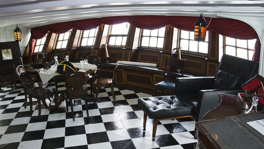
While the furniture etc is difficult, the floor patterning is easy, so I added that and then the painting and decoration should suffice for the limited view through the small windows at the back of the ship. Below is the rear gallery area and shows some of the congested, limited space inside. You can see the floor apttern and some of the wall decorations.
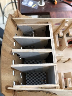
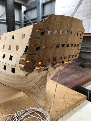
The lighting through the rear windows is subtle, and arranged without any 'geometry' to suggest the random patterning of where lights would be. Although you cannot see it in the photo below, these LED lights flicker, to simulate candle-lit lanterns. Note too in this photo, that the rear internal 'skin' of the rear gallery is pinned by brass tacks to position it before final gluing.
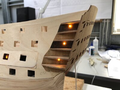
The following picture shows the side galleries and the installation of the flickering LEDs in these spaces.
The next stage is the fitting of the 'outside' skins of the side galleries. This is made a little tricky because the individual windows have to have clear acetate added to provide windows. At this stage, I am grappling with this, because the Manual says to glue acetate, clear sheet to the insides and while this is OK for the window panes, it is not accurate to the actual ship. Below is a photo from the actual ship which shows mullions (or muntin bars) and window framing which is not present in the Caldercraft kit. (NOTE AFTER POSTING: In fact, this is NOT correct. Caldercraft HAVE provided window mouldings and these are on a Brass Sheet I had not realised - See my post a week later).
I will need to give this some more thought.

Regards,
PeterG
Elapsed time = 285 hours
Now, for those who have been following my Build Log, you will remember that I have wanted to place internal lights into the model. For the rear galleries, obviously, the various windows look into the rooms at the stern of the ship, and in there would be lighting, so my next step, before attaching the gallery timbers which will enclose these spaces, I have to add wiring and flickering LEDs to these spaces. The wiring from the gun ports of the lower gun decks is easily accessible at this stage and so it was a relatively easy job to mount some LEDs and extend the wiring. The internal lighting will also allow rear viewing through the windows (portholes ??) of the galleries and so some internal detail will be required.
I painted the lit section spaces and added some wall decoration and floor patterning as per some photos of the internal fitout of the actual ship (for example, see below):

While the furniture etc is difficult, the floor patterning is easy, so I added that and then the painting and decoration should suffice for the limited view through the small windows at the back of the ship. Below is the rear gallery area and shows some of the congested, limited space inside. You can see the floor apttern and some of the wall decorations.

The lighting through the rear windows is subtle, and arranged without any 'geometry' to suggest the random patterning of where lights would be. Although you cannot see it in the photo below, these LED lights flicker, to simulate candle-lit lanterns. Note too in this photo, that the rear internal 'skin' of the rear gallery is pinned by brass tacks to position it before final gluing.

The following picture shows the side galleries and the installation of the flickering LEDs in these spaces.

The next stage is the fitting of the 'outside' skins of the side galleries. This is made a little tricky because the individual windows have to have clear acetate added to provide windows. At this stage, I am grappling with this, because the Manual says to glue acetate, clear sheet to the insides and while this is OK for the window panes, it is not accurate to the actual ship. Below is a photo from the actual ship which shows mullions (or muntin bars) and window framing which is not present in the Caldercraft kit. (NOTE AFTER POSTING: In fact, this is NOT correct. Caldercraft HAVE provided window mouldings and these are on a Brass Sheet I had not realised - See my post a week later).
I will need to give this some more thought.

Regards,
PeterG
Elapsed time = 285 hours
Last edited:
Before we start covering the aft galleries, pay attention to the stern. There shouldn't be such a breakLatest update a little slow as I have been battling with the slot sizes and fitting of the various parts of the stern galleries (see previous post). I have managed to get it all together and while the slot sizes have been modified and it all looks OK, the gluing of the bits will make a solid structure and it should be satisfactory going forward.
Now, for those who have been following my Build Log, you will remember that I have wanted to place internal lights into the model. For the rear galleries, obviously, the various windows look into the rooms at the stern of the ship, and in there would be lighting, so my next step, before attaching the gallery timbers which will enclose these spaces, I have to add wiring and flickering LEDs to these spaces. The wiring from the gun ports of the lower gun decks is easily accessible at this stage and so it was a relatively easy job to mount some LEDs and extend the wiring. The internal lighting will also allow rear viewing through the windows (portholes ??) of the galleries and so some internal detail will be required.
I painted the lit section spaces and added some wall decoration and floor patterning as per some photos of the internal fitout of the actual ship (for example, see below):
View attachment 437695
While the furniture etc is difficult, the floor patterning is easy, so I added that and then the painting and decoration should suffice for the limited view through the small windows at the back of the ship. Below is the rear gallery area and shows some of the congested, limited space inside. You can see the floor apttern and some of the wall decorations.
View attachment 437696
The lighting through the rear windows is subtle, and arranged without any 'geometry' to suggest the random patterning of where lights would be. Although you cannot see it in the photo below, these LED lights flicker, to simulate candle-lit lanterns. Note too in this photo, that the rear internal 'skin' of the rear gallery is pinned by brass tacks to position it before final gluing.
View attachment 437697
The following picture shows the side galleries and the installation of the flickering LEDs in these spaces.
View attachment 437698
The next stage is the fitting of the 'outside' skins of the side galleries. This is made a little tricky because the individual windows have to have clear acetate added to provide windows. At this stage, I am grappling with this, because the Manual says to glue acetate, clear sheet to the insides and while this is OK for the window panes, it is not accurate to the actual ship. Below is a photo from the actual ship which shows mullions (or muntin bars) and window framing which is not present in the Caldercraft kit. I will need to give this some more thought.
View attachment 437701
Regards,
PeterG
Elapsed time = 285 hours

I've used the smallest available styrene strip to make mullions, using canopy glue, on my Le Superbe.Latest update a little slow as I have been battling with the slot sizes and fitting of the various parts of the stern galleries (see previous post). I have managed to get it all together and while the slot sizes have been modified and it all looks OK, the gluing of the bits will make a solid structure and it should be satisfactory going forward.
Now, for those who have been following my Build Log, you will remember that I have wanted to place internal lights into the model. For the rear galleries, obviously, the various windows look into the rooms at the stern of the ship, and in there would be lighting, so my next step, before attaching the gallery timbers which will enclose these spaces, I have to add wiring and flickering LEDs to these spaces. The wiring from the gun ports of the lower gun decks is easily accessible at this stage and so it was a relatively easy job to mount some LEDs and extend the wiring. The internal lighting will also allow rear viewing through the windows (portholes ??) of the galleries and so some internal detail will be required.
I painted the lit section spaces and added some wall decoration and floor patterning as per some photos of the internal fitout of the actual ship (for example, see below):
View attachment 437695
While the furniture etc is difficult, the floor patterning is easy, so I added that and then the painting and decoration should suffice for the limited view through the small windows at the back of the ship. Below is the rear gallery area and shows some of the congested, limited space inside. You can see the floor apttern and some of the wall decorations.
View attachment 437696
The lighting through the rear windows is subtle, and arranged without any 'geometry' to suggest the random patterning of where lights would be. Although you cannot see it in the photo below, these LED lights flicker, to simulate candle-lit lanterns. Note too in this photo, that the rear internal 'skin' of the rear gallery is pinned by brass tacks to position it before final gluing.
View attachment 437697
The following picture shows the side galleries and the installation of the flickering LEDs in these spaces.
View attachment 437698
The next stage is the fitting of the 'outside' skins of the side galleries. This is made a little tricky because the individual windows have to have clear acetate added to provide windows. At this stage, I am grappling with this, because the Manual says to glue acetate, clear sheet to the insides and while this is OK for the window panes, it is not accurate to the actual ship. Below is a photo from the actual ship which shows mullions (or muntin bars) and window framing which is not present in the Caldercraft kit. I will need to give this some more thought.
View attachment 437701
Regards,
PeterG
Elapsed time = 285 hours
Has anyone tried making 'anchor stock' strips for the wales, if so, how successfully?Before we start covering the aft galleries, pay attention to the stern. There shouldn't be such a break
View attachment 437731View attachment 437732
Thank you Alexander74 for highlighting the abrupt edge of the first planking over the Bulkhead 17 at the stern of the ship. I examined it and although it is probably sharper than it should be, the camera angle doesn't help but I have also sanded it flatter, and it now looks OK. I think the second planking too, should softer the angle.
Thank you Stuart Little also, for helping with the suggestions regarding the stern gallery mullions. I have researched this long and hard but in the end, I thought, "I couldn't believe Caldercraft would not have addressed this".
Sure enough, to their credit, they have!! In the 0.5mm Brass Etched Sheet (2), are the window inserts with the formed mullions for the side and aft galleries.

So, this will solve a lot of work. I can therefore go ahead and shape/glue the various parts of the side gallery ' skins' and move forward.
I have started to plank the decking of the gun deck and this is getting done with a timber (Obechi) which I had from another kit with the same dimension (4mm wide by 1 mm thick). This timber is lighter than the Caldercraft supplied decking timber and I think more closely matches what I have seen in pictures of the gun deck timber flooring in website pictures. Only scant viewing of the Lower Gun Deck flooring is observable from above in any case, so I think it will be OK.

I have used paul1956 approach and cut lengths to produce the 4x planking pattern and this is working well. I will progress the deck planking across the deck and leave allowance for the Main Mast which must pass through this deck and have a 'ring' collar where it penetrates the deck. This decking extends from Bulkheads 4 to 12 with some extensions into the side entry openings and this will be easily done.
Regards,
PeterG
Elapsed Time = 302 Hours
Thank you Stuart Little also, for helping with the suggestions regarding the stern gallery mullions. I have researched this long and hard but in the end, I thought, "I couldn't believe Caldercraft would not have addressed this".
Sure enough, to their credit, they have!! In the 0.5mm Brass Etched Sheet (2), are the window inserts with the formed mullions for the side and aft galleries.

So, this will solve a lot of work. I can therefore go ahead and shape/glue the various parts of the side gallery ' skins' and move forward.
I have started to plank the decking of the gun deck and this is getting done with a timber (Obechi) which I had from another kit with the same dimension (4mm wide by 1 mm thick). This timber is lighter than the Caldercraft supplied decking timber and I think more closely matches what I have seen in pictures of the gun deck timber flooring in website pictures. Only scant viewing of the Lower Gun Deck flooring is observable from above in any case, so I think it will be OK.

I have used paul1956 approach and cut lengths to produce the 4x planking pattern and this is working well. I will progress the deck planking across the deck and leave allowance for the Main Mast which must pass through this deck and have a 'ring' collar where it penetrates the deck. This decking extends from Bulkheads 4 to 12 with some extensions into the side entry openings and this will be easily done.
Regards,
PeterG
Elapsed Time = 302 Hours
Last edited:
I notice, from photos, that Vic's decks are more of a 'driftwood grey' colour. I've got some Driftwood Dove Grey dye from Littlefair, here in UK, which I've been using on decks.Thank you Alexander74 for highlighting the abrupt edge of the first planking over the Bulkhead 17 at the stern of the ship. I examined it and although it is probably sharper than it should be, the camera angle doesn't help but I have also sanded it flatter, and it now looks OK. I think the second planking too, should softer the angle.
Thank you Stuart Little also, for helping with the suggestions regarding the stern gallery mullions. I have researched this long and hard but in the end, I thought, "I couldn't believe Caldercraft would not have addressed this".
Sure enough, to their credit, they have!! In the 0.5mm Brass Etched Sheet (2), are the window inserts with the formed mullions for the side and aft galleries.
View attachment 439747
So, this will solve a lot of work. I can therefore go ahead and shape/glue the various parts of the side gallery ' skins' and move forward.
I have started to plank the decking of the gun deck and this is getting done with a timber (Obechi) which I had from another kit with the same dimension (4mm wide by 1 mm thick). This timber is lighter than the Caldercraft supplied decking timber and I think more closely matches what I have seen in pictures of the gun deck timber flooring in website pictures. Only scant viewing of the Gun Deck flooring is observable from above in any case, so I think it will be OK.
View attachment 439748
I have used paul1956 approach and cut lengths to produce the 4x planking pattern and this is working well. I will progress the deck planking across the deck and leave allowance for the Main Mast which must pass through this deck and have a 'ring' collar where it penetrates the deck. This decking extends from Bulkheads 4 to 12 with some extensions into the side entry openings and this will be easily done.
Regards,
PeterG
Elapsed Time = 302 Hours
Thank you Stuart Little. Some of the images I have seen are a light grey colour, I agree, but others are a bit of a darker brown (a lot like Obechi). For example, below are a couple of gun deck examples and they are significantly different. I suspect its the ambient light, direction of the photo and computer rendering etc vary the colour a lot.

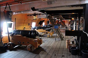
I finished the Lower Gun Deck planking yesterday and used a matt clear varnish to finish off and it does look OK, so I am going with it as it is. Refer to my previous post, I think it looks quite satisfactory. I will be installing the door entry linings and door entry flooring today plus the gallery skins. Photos to follow.
Regards,
PeterG
Elapsed Time: 307 hours
Last edited:
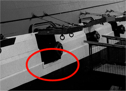
I have moved on to the second planking and as per the instructions, a line created between the gun ports (from Plan 2) is used to define the line of the first and subsequent planks. I have placed a few planks on the port side which get to a point of partially covering the gun ports. These have to be cut out as you progress (otherwise you lose where they are!!). Cutting these out just using a scalpel and with the walnut that the kit supplies is hard work. The walnut is a hard wood!! So to assist I created a gun port outline which I manually position over the gun port position and then drill around as below:
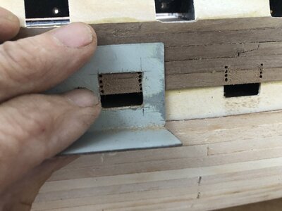
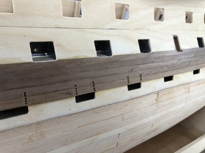
With the holes drilled, I can then easily cut and carefully shape the walnut second plank linings around the gun ports as defined by the plywood inner template. Note too that I have used scarf jointing rather than butt joints of the planks. I felt this was closer to reality and having seen some of the photos by Jupiter913 recently posted, this appears to be accurate (see below).
Best Regards,
PeterG


With the holes drilled, I can then easily cut and carefully shape the walnut second plank linings around the gun ports as defined by the plywood inner template. Note too that I have used scarf jointing rather than butt joints of the planks. I felt this was closer to reality and having seen some of the photos by Jupiter913 recently posted, this appears to be accurate (see below).

Best Regards,
PeterG
Excellent build and log. Loving it.
I omitted earlier, a stage of the Victory build which provides for the galleries and rear/stern area of the model. I found the side galleries to be especially difficult because they need to be dry fitted initially to be correct and your dealing with about 12 individual pieces per side. Hence it was difficult to get right. The other thing about it is that the three gallery facings (per side) which hold the windows, have to have their internal panes of clear material put into place and glued. PVA or other glue must be used (not cryroacrylate as it melts and 'fogs' the clear plastic material.)
The other aspect of the build here of course, is that these are gallery windows into the internals of the ship, and as I have decided to internally light the ship with LEDs, these had to be fitted and wired/connected in place.
Finally got it done with a bit of judicious sanding and shaping and the result is below:
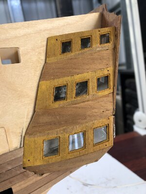
I had put some 'Yellow' Ochre' on the linings of the galleries to get a 'feel' for the colours I am going to have to paint with eventually, but in the above, these galleries are completely covered, so it won't show in any case. The exercise told me that I will have to use an undercoat before painting the ochre and black hull sides of the ship - more experimenting required.
So, onward with second planking. I am making my way slowly down the sides of the hull using the contact glue approach of Paul Vickers, rather than the suggested CA glue method recommended in the Manual. This glue is a Sika product and I am finding it excellent.

I chose Paul's method for the following reasons.
A) It can be relatively slow with 5-10 minutes of contact time before it really 'goes off' and fixes the plank in place, so there is great flexibility if you get it wrong or need to adjust as fitting the planks.
B) It can be easily applied with paintbrush or cotton bud (so doesn't ruin brushes) and can be easily cleaned using acetone or by rubbing once dry.
C) Its a LOT cheaper than CA glue.
D) One negative of the gluing process is that it REQUIRES you to apply glue to BOTH the hull and the plank surfaces, then leave for 3-5 minutes. It is not possible to get the area to be planked exactly covered with glue where the plank goes, but if you cover an area even where it's not (at that stage) being planked, it doesn't matter. It just hardens and when you later plank the area, it still sticks well. Many thanks to Paul Vickers for this tip.
Two other issues have arisen with the second planking that I wasn't expecting:
BENDING THE WALNUT PLANKS
The timber provided in the Caldercraft kit is walnut. It is of high quality, 1 x 5 mm and an excellent finish to the model. However, it is hard and relatively inflexible even after 5-10 minutes of cold or hot water soaking. It can be bent, but with just soaking, I have broken a couple of planks near the high curvature bow. So, to get around this, I have reverted back to the old close cut pliers and insert 'crease' cuts across the plank where tight curvature is required. These cuts use the pliers (see below) which cut about half way through with cuts at about 0.5 cm along the plank.
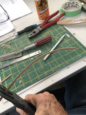
In the picture above, you can see the curvature developing and the numerous cuts placed by the bladed pliers.
CUTTING THE WALNUT FOR TAPERING
As we move down the hull, some planks have to be tapered. I have attempted to use a stainless steel ruler and scalpel or sharp blade approach and have found this really difficult. Because the walnut is described as "a tough hardwood of medium density, with moderate bending and crushing strengths, and low stiffness", (quote from the American Hardwoods Information Center), the simple cutting along or at an angle to the grain, it is extremely difficult as it tends to 'pull' the wood plank without cutting or scoring. You can increase the pressure on the ruler to hold the plank down, but when the cut gets to the tapered fine end, the wood tends to split.
I thought I could machine cut it and while this works, it is slow and not accurate where fine tapering is required.
So, on thinking about it, I figured I might be able to make a jig to accurately cut a tapered hardwood by clamping the plank. The timber size is 1 x 5 mm, so I got some 1 mm sheet metal and bought a square of some MDF timber, some angle aluminium, a new steel ruler and a couple of bolts and wingnuts. Below is my jig.
The sheet metal was cut into two unequal width plates and I ensured the edge surfaces were very flat and straight. I fixed ONE plate to the timber base with screws and routed two slots into the second metal sheet to allow it to have side movement when unscrewed using the bolt/wingnut release. I drilled two appropriate (6mm) bolt holes under the routed plate slots into the timber so the second plate could move laterally, but be locked down by the wingnuts and washers. I then secured the angle aluminium to the end of the base timber (with the upper edge vertically level with the 1 mm plates). I then routed another slot into the aluminium and fixed the end of the stainless steel ruler by a bolt/wingnut through the slot. The slots are to allow variation for different thicknesses or widths of timber. A future possible improvement could be a method of locking the moveable, unattached end of the ruler, but I found in practice I did not need this.
I now had a jig which could lock a plank lying flat by side pressure clamping of the steel plates, and then over the top, position the ruler at an angle to allow an accurate taper cut with a sharp scalpel along or at a near angle to the timber grain. The two pictures below show how this works.
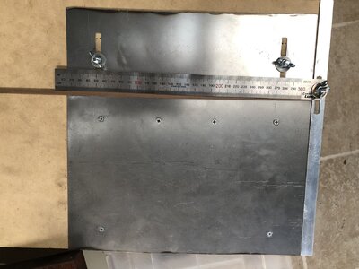
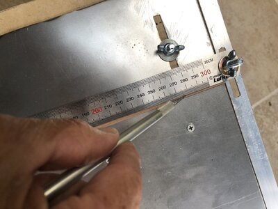
I was surprised how well this worked. You might have to score walnut with the scalpel a few times to cut all the way through the plank and you have to stop the cut just before it intersects with the steel locking plate, but the jig locks the plank tightly in place and allows an accurate cut which is clean and as thin as you want.
I am going to have to produce a LOT of tapered planks, so this should help immensely. I still have to use the bending cuts to allow the required curvatures, but the process is fast and effective.
Best Regards,
Peter G.
Elapsed Time : 385 hours
The other aspect of the build here of course, is that these are gallery windows into the internals of the ship, and as I have decided to internally light the ship with LEDs, these had to be fitted and wired/connected in place.
Finally got it done with a bit of judicious sanding and shaping and the result is below:

I had put some 'Yellow' Ochre' on the linings of the galleries to get a 'feel' for the colours I am going to have to paint with eventually, but in the above, these galleries are completely covered, so it won't show in any case. The exercise told me that I will have to use an undercoat before painting the ochre and black hull sides of the ship - more experimenting required.
So, onward with second planking. I am making my way slowly down the sides of the hull using the contact glue approach of Paul Vickers, rather than the suggested CA glue method recommended in the Manual. This glue is a Sika product and I am finding it excellent.

I chose Paul's method for the following reasons.
A) It can be relatively slow with 5-10 minutes of contact time before it really 'goes off' and fixes the plank in place, so there is great flexibility if you get it wrong or need to adjust as fitting the planks.
B) It can be easily applied with paintbrush or cotton bud (so doesn't ruin brushes) and can be easily cleaned using acetone or by rubbing once dry.
C) Its a LOT cheaper than CA glue.
D) One negative of the gluing process is that it REQUIRES you to apply glue to BOTH the hull and the plank surfaces, then leave for 3-5 minutes. It is not possible to get the area to be planked exactly covered with glue where the plank goes, but if you cover an area even where it's not (at that stage) being planked, it doesn't matter. It just hardens and when you later plank the area, it still sticks well. Many thanks to Paul Vickers for this tip.
Two other issues have arisen with the second planking that I wasn't expecting:
BENDING THE WALNUT PLANKS
The timber provided in the Caldercraft kit is walnut. It is of high quality, 1 x 5 mm and an excellent finish to the model. However, it is hard and relatively inflexible even after 5-10 minutes of cold or hot water soaking. It can be bent, but with just soaking, I have broken a couple of planks near the high curvature bow. So, to get around this, I have reverted back to the old close cut pliers and insert 'crease' cuts across the plank where tight curvature is required. These cuts use the pliers (see below) which cut about half way through with cuts at about 0.5 cm along the plank.

In the picture above, you can see the curvature developing and the numerous cuts placed by the bladed pliers.
CUTTING THE WALNUT FOR TAPERING
As we move down the hull, some planks have to be tapered. I have attempted to use a stainless steel ruler and scalpel or sharp blade approach and have found this really difficult. Because the walnut is described as "a tough hardwood of medium density, with moderate bending and crushing strengths, and low stiffness", (quote from the American Hardwoods Information Center), the simple cutting along or at an angle to the grain, it is extremely difficult as it tends to 'pull' the wood plank without cutting or scoring. You can increase the pressure on the ruler to hold the plank down, but when the cut gets to the tapered fine end, the wood tends to split.
I thought I could machine cut it and while this works, it is slow and not accurate where fine tapering is required.
So, on thinking about it, I figured I might be able to make a jig to accurately cut a tapered hardwood by clamping the plank. The timber size is 1 x 5 mm, so I got some 1 mm sheet metal and bought a square of some MDF timber, some angle aluminium, a new steel ruler and a couple of bolts and wingnuts. Below is my jig.
The sheet metal was cut into two unequal width plates and I ensured the edge surfaces were very flat and straight. I fixed ONE plate to the timber base with screws and routed two slots into the second metal sheet to allow it to have side movement when unscrewed using the bolt/wingnut release. I drilled two appropriate (6mm) bolt holes under the routed plate slots into the timber so the second plate could move laterally, but be locked down by the wingnuts and washers. I then secured the angle aluminium to the end of the base timber (with the upper edge vertically level with the 1 mm plates). I then routed another slot into the aluminium and fixed the end of the stainless steel ruler by a bolt/wingnut through the slot. The slots are to allow variation for different thicknesses or widths of timber. A future possible improvement could be a method of locking the moveable, unattached end of the ruler, but I found in practice I did not need this.
I now had a jig which could lock a plank lying flat by side pressure clamping of the steel plates, and then over the top, position the ruler at an angle to allow an accurate taper cut with a sharp scalpel along or at a near angle to the timber grain. The two pictures below show how this works.


I was surprised how well this worked. You might have to score walnut with the scalpel a few times to cut all the way through the plank and you have to stop the cut just before it intersects with the steel locking plate, but the jig locks the plank tightly in place and allows an accurate cut which is clean and as thin as you want.
I am going to have to produce a LOT of tapered planks, so this should help immensely. I still have to use the bending cuts to allow the required curvatures, but the process is fast and effective.
Best Regards,
Peter G.
Elapsed Time : 385 hours
Good morning Peter. I remember cutting those gun ports….over a 100I have moved on to the second planking and as per the instructions, a line created between the gun ports (from Plan 2) is used to define the line of the first and subsequent planks. I have placed a few planks on the port side which get to a point of partially covering the gun ports. These have to be cut out as you progress (otherwise you lose where they are!!). Cutting these out just using a scalpel and with the walnut that the kit supplies is hard work. The walnut is a hard wood!! So to assist I created a gun port outline which I manually position over the gun port position and then drill around as below:
View attachment 441909
View attachment 441910
With the holes drilled, I can then easily cut and carefully shape the walnut second plank linings around the gun ports as defined by the plywood inner template. Note too that I have used scarf jointing rather than butt joints of the planks. I felt this was closer to reality and having seen some of the photos by Jupiter913 recently posted, this appears to be accurate (see below).
View attachment 441911
Best Regards,
PeterG
Wow, Caldercraft has produced a fantastic stern gallery design and quality. (Definitely the best Victory kit out there). Non the less that stern on the Victory is a challenge and you are owning it. Cool jig for tapering the planks BTW. Cheers GrantI omitted earlier, a stage of the Victory build which provides for the galleries and rear/stern area of the model. I found the side galleries to be especially difficult because they need to be dry fitted initially to be correct and your dealing with about 12 individual pieces per side. Hence it was difficult to get right. The other thing about it is that the three gallery facings (per side) which hold the windows, have to have their internal panes of clear material put into place and glued. PVA or other glue must be used (not cryroacrylate as it melts and 'fogs' the clear plastic material.)
The other aspect of the build here of course, is that these are gallery windows into the internals of the ship, and as I have decided to internally light the ship with LEDs, these had to be fitted and wired/connected in place.
Finally got it done with a bit of judicious sanding and shaping and the result is below:
View attachment 442747
I had put some 'Yellow' Ochre' on the linings of the galleries to get a 'feel' for the colours I am going to have to paint with eventually, but in the above, these galleries are completely covered, so it won't show in any case. The exercise told me that I will have to use an undercoat before painting the ochre and black hull sides of the ship - more experimenting required.
So, onward with second planking. I am making my way slowly down the sides of the hull using the contact glue approach of Paul Vickers, rather than the suggested CA glue method recommended in the Manual. This glue is a Sika product and I am finding it excellent.
View attachment 442748
I chose Paul's method for the following reasons.
A) It can be relatively slow with 5-10 minutes of contact time before it really 'goes off' and fixes the plank in place, so there is great flexibility if you get it wrong or need to adjust as fitting the planks.
B) It can be easily applied with paintbrush or cotton bud (so doesn't ruin brushes) and can be easily cleaned using acetone or by rubbing once dry.
C) Its a LOT cheaper than CA glue.
D) One negative of the gluing process is that it REQUIRES you to apply glue to BOTH the hull and the plank surfaces, then leave for 3-5 minutes. It is not possible to get the area to be planked exactly covered with glue where the plank goes, but if you cover an area even where it's not (at that stage) being planked, it doesn't matter. It just hardens and when you later plank the area, it still sticks well. Many thanks to Paul Vickers for this tip.
Two other issues have arisen with the second planking that I wasn't expecting:
BENDING THE WALNUT PLANKS
The timber provided in the Caldercraft kit is walnut. It is of high quality, 1 x 5 mm and an excellent finish to the model. However, it is hard and relatively inflexible even after 5-10 minutes of cold or hot water soaking. It can be bent, but with just soaking, I have broken a couple of planks near the high curvature bow. So, to get around this, I have reverted back to the old close cut pliers and insert 'crease' cuts across the plank where tight curvature is required. These cuts use the pliers (see below) which cut about half way through with cuts at about 0.5 cm along the plank.
View attachment 442752
In the picture above, you can see the curvature developing and the numerous cuts placed by the bladed pliers.
CUTTING THE WALNUT FOR TAPERING
As we move down the hull, some planks have to be tapered. I have attempted to use a stainless steel ruler and scalpel or sharp blade approach and have found this really difficult. Because the walnut is described as "a tough hardwood of medium density, with moderate bending and crushing strengths, and low stiffness", (quote from the American Hardwoods Information Center), the simple cutting along or at an angle to the grain, it is extremely difficult as it tends to 'pull' the wood plank without cutting or scoring. You can increase the pressure on the ruler to hold the plank down, but when the cut gets to the tapered fine end, the wood tends to split.
I thought I could machine cut it and while this works, it is slow and not accurate where fine tapering is required.
So, on thinking about it, I figured I might be able to make a jig to accurately cut a tapered hardwood by clamping the plank. The timber size is 1 x 5 mm, so I got some 1 mm sheet metal and bought a square of some MDF timber, some angle aluminium, a new steel ruler and a couple of bolts and wingnuts. Below is my jig.
The sheet metal was cut into two unequal width plates and I ensured the edge surfaces were very flat and straight. I fixed ONE plate to the timber base with screws and routed two slots into the second metal sheet to allow it to have side movement when unscrewed using the bolt/wingnut release. I drilled two appropriate (6mm) bolt holes under the routed plate slots into the timber so the second plate could move laterally, but be locked down by the wingnuts and washers. I then secured the angle aluminium to the end of the base timber (with the upper edge vertically level with the 1 mm plates). I then routed another slot into the aluminium and fixed the end of the stainless steel ruler by a bolt/wingnut through the slot. The slots are to allow variation for different thicknesses or widths of timber. A future possible improvement could be a method of locking the moveable, unattached end of the ruler, but I found in practice I did not need this.
I now had a jig which could lock a plank lying flat by side pressure clamping of the steel plates, and then over the top, position the ruler at an angle to allow an accurate taper cut with a sharp scalpel along or at a near angle to the timber grain. The two pictures below show how this works.
View attachment 442753
View attachment 442754
I was surprised how well this worked. You might have to score walnut with the scalpel a few times to cut all the way through the plank and you have to stop the cut just before it intersects with the steel locking plate, but the jig locks the plank tightly in place and allows an accurate cut which is clean and as thin as you want.
I am going to have to produce a LOT of tapered planks, so this should help immensely. I still have to use the bending cuts to allow the required curvatures, but the process is fast and effective.
Best Regards,
Peter G.
Elapsed Time : 385 hours
Very clever jig, Peter!
Many thanks Paul and Grant. The jig has saved an enormous amount of shaping and tapering time. Almost every plank comes out accurately and without the need, other than a quick edge sand, ready for placement and gluing. The contact cement I am using is excellent, allows for an unhurried adjustment if required, but once pressured to the first planking, it adheres really well and permanently. I am using Sikaflex Contact Glue which is widely available and not overly expensive.
Following Paul Vicker's advice, I apply the glue to both hull and plank to be added, sometimes 3-4 planks, and in that time, I can then place the new plank, ensure it is correctly positioned and then apply pressure to make permanent. I have reached a point of about 3/4 second plank coverage and have completed the planking to below the waterline with tapers and no spoilers. Beneath this (which will be covered by coppering), I have changed the plank alignment and shape to permit full length planks (with overhang at the stern). This is much quicker and means the planks align themselves with less 'cross-grain' pressure. I only then have to cut the long ends at the stern as I need to later on.
...and here is the stern with the overhanging planks. There are couple of spoilers needed in this end to fill the gaps, but nothing major and the shaping and insertion is relatively easy. The walnut timber is a pleasure to work with, albeit a hardwood, but it seems to bend and fit the first planking without too much required nailing or weighting.

Note that in the photo above, the emerging wire, is the power feed-in for the internal LED lighting which I have discussed earlier. More of this will be required as additional deck levels are added.
Unfortunately, the planking is overall quite slow. It takes about 2-3 hours for me to bend, shape and position/glue 4-6 planks at a session, so updates are coming slower than I would like, but 'no rush'. I also have some personal commitments coming up which will take a lot of time, to slow progress even further. Please bear with me....
Regards,
PeterG
Elapsed Time: 405 hours
Following Paul Vicker's advice, I apply the glue to both hull and plank to be added, sometimes 3-4 planks, and in that time, I can then place the new plank, ensure it is correctly positioned and then apply pressure to make permanent. I have reached a point of about 3/4 second plank coverage and have completed the planking to below the waterline with tapers and no spoilers. Beneath this (which will be covered by coppering), I have changed the plank alignment and shape to permit full length planks (with overhang at the stern). This is much quicker and means the planks align themselves with less 'cross-grain' pressure. I only then have to cut the long ends at the stern as I need to later on.

...and here is the stern with the overhanging planks. There are couple of spoilers needed in this end to fill the gaps, but nothing major and the shaping and insertion is relatively easy. The walnut timber is a pleasure to work with, albeit a hardwood, but it seems to bend and fit the first planking without too much required nailing or weighting.

Note that in the photo above, the emerging wire, is the power feed-in for the internal LED lighting which I have discussed earlier. More of this will be required as additional deck levels are added.
Unfortunately, the planking is overall quite slow. It takes about 2-3 hours for me to bend, shape and position/glue 4-6 planks at a session, so updates are coming slower than I would like, but 'no rush'. I also have some personal commitments coming up which will take a lot of time, to slow progress even further. Please bear with me....
Regards,
PeterG
Elapsed Time: 405 hours
Sorry about the long delay between posts in this Build Log - A lot going on in our everyday lives!!
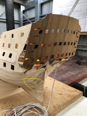
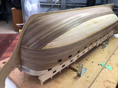
Well the final, second planking (at least up to the Upper Gun Deck is complete). I am pleased how it came out. Below are a couple of images of the second planking:
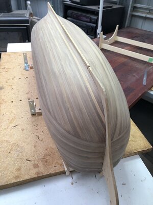
Note that the break of plank angle to fore-and-aft near the keel, is BELOW the waterline, so will be hidden by the copper plating (as it is not accurate to the ship!!)
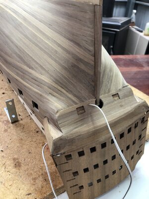
In the kit, the stern counter is a flat piece of walnut (with the ports located on both sides. On examining some photos of the actual ship however, the rear counter appears to have horizontal planking below the aft galleries. So, I have opted to plank the counter and inserted the ports in the correct location. The counter is painted black on the ship so the planking is difficult to see, but having it there I think is more accurate.
Please excuse the rear exit of the power wiring for the LED internal lighting. It will be more hidden in the future.
The following step is to add the Upper Gun Deck. This is a tricky stage as there is little room for manoevreing it and it needs to either be a) bent into a near half-circle to squeeze in around the bulwarks or b) cut along its outer bulwark slots to allow it to pass into the hull. I opted to squeeze it into a semicircle and with a lot of moving and tight fitting, it finally went in correctly and with some glue in place to hold it down on the bulwark cross supports.
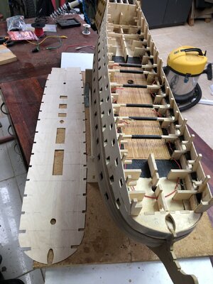
Note in the images, that I have fed the wiring for the LED lights through to make connections for lights in the upper decks. The lower deck LEDs are now all installed and operational.
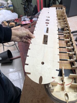
Once in place, I positioned the three masts to be sure they correctly aligned and could be angled appropriately with the correct rake angle.
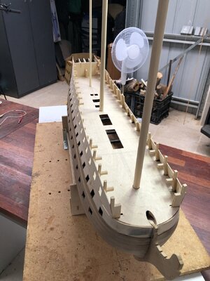
The next stage is to place the inner bulwark gun templates for the Upper Gun Deck. These are fitted above the Upper Gun Deck but on the inside of the deck. The positions of these is critical because there has to be an alignment of the gun ports to allow correct lining of these ports through the hull.
Elapsed time: 425 hours
Regards,
PeterG
Well the final, second planking (at least up to the Upper Gun Deck is complete). I am pleased how it came out. Below are a couple of images of the second planking:

Note that the break of plank angle to fore-and-aft near the keel, is BELOW the waterline, so will be hidden by the copper plating (as it is not accurate to the ship!!)

In the kit, the stern counter is a flat piece of walnut (with the ports located on both sides. On examining some photos of the actual ship however, the rear counter appears to have horizontal planking below the aft galleries. So, I have opted to plank the counter and inserted the ports in the correct location. The counter is painted black on the ship so the planking is difficult to see, but having it there I think is more accurate.
Please excuse the rear exit of the power wiring for the LED internal lighting. It will be more hidden in the future.
The following step is to add the Upper Gun Deck. This is a tricky stage as there is little room for manoevreing it and it needs to either be a) bent into a near half-circle to squeeze in around the bulwarks or b) cut along its outer bulwark slots to allow it to pass into the hull. I opted to squeeze it into a semicircle and with a lot of moving and tight fitting, it finally went in correctly and with some glue in place to hold it down on the bulwark cross supports.

Note in the images, that I have fed the wiring for the LED lights through to make connections for lights in the upper decks. The lower deck LEDs are now all installed and operational.

Once in place, I positioned the three masts to be sure they correctly aligned and could be angled appropriately with the correct rake angle.

The next stage is to place the inner bulwark gun templates for the Upper Gun Deck. These are fitted above the Upper Gun Deck but on the inside of the deck. The positions of these is critical because there has to be an alignment of the gun ports to allow correct lining of these ports through the hull.
Elapsed time: 425 hours
Regards,
PeterG
Last edited:
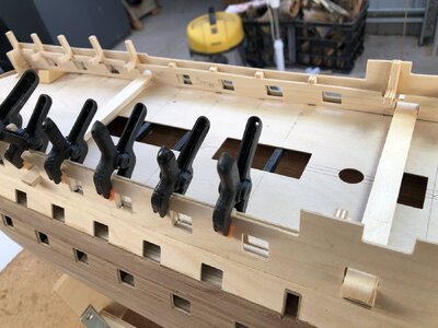
Fitting of the Upper Gun Deck internal gun port templates again was tricky as the horizontal AND vertical positioning required an alignment through the ports to allow port linings to be fitted correctly. As it happens a tip from Paul Vickers (thanks Paul) was to use some available 6mm plywood strips which could then be passed through the Upper Gun Deck to allow a direct, through hull fitting position of the Gun Port templates on both the port and starboard sides (see below).
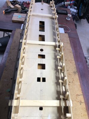
As it happens I had to cut a few millimetres off the bottom of these templates to enable them to fit neatly and at the correct height. Once in place, it was an easy process to glue the bulwark faces and fix the templates in place.
Once the Upper Gun Deck templates were correctly positioned and glued, I could then start fitting the linings to the eight gun ports which have no recess to the hull as these ports have no swinging gun port doors. These are the only ports on the Upper Gun Deck that have this arrangement. The rest (two forward and five aft), have swinging gun doors and therefore a recessed lining through to the bulwarks from the outer hull.
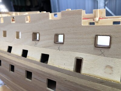
When completed, I added some additional walnut planks to extend the height of the second planking. As I went, I had to cut out the gun ports for each level, and this took considerable time to do correctly and accurately. A lot of scalpel and sharp knife work!! With the use of the drill to initially mark out the gun port margins, they came out OK, but it takes some time. The final process is to use a fine flat wood file to ensure all surfaces and outer hull planking are aligned and smooth.
Elapsed time: 520 hours
Best Regards,
PeterG

As it happens I had to cut a few millimetres off the bottom of these templates to enable them to fit neatly and at the correct height. Once in place, it was an easy process to glue the bulwark faces and fix the templates in place.

Once the Upper Gun Deck templates were correctly positioned and glued, I could then start fitting the linings to the eight gun ports which have no recess to the hull as these ports have no swinging gun port doors. These are the only ports on the Upper Gun Deck that have this arrangement. The rest (two forward and five aft), have swinging gun doors and therefore a recessed lining through to the bulwarks from the outer hull.

When completed, I added some additional walnut planks to extend the height of the second planking. As I went, I had to cut out the gun ports for each level, and this took considerable time to do correctly and accurately. A lot of scalpel and sharp knife work!! With the use of the drill to initially mark out the gun port margins, they came out OK, but it takes some time. The final process is to use a fine flat wood file to ensure all surfaces and outer hull planking are aligned and smooth.
Elapsed time: 520 hours
Best Regards,
PeterG
Last edited:


