CAF Granado 1/48 PoF Bomb Vessel by Signet

I'm rewriting this as a correction. Part 1-a is exactly what it says. There is no parts 1-b, 1-c or 1-d. The next row starts at 2-a. I hadn't counted right.
1722029941921.png
It's still a bit confusing to me that there are FOUR (4) parts 1-a. Not sure why that would be the case, but it is. I'll proceed accordingly.

Sorry for posting erroneous information on the forums. I couldn't find a Delete Post function.
 
Last edited:
I have to confess that using a belt sander on the top of my frames never occurred to me. Aggressive :D! Glad that worked out!
It's not quite as bad as it sounds. It's only a 1/2" wide belt, is easily hand-held, and variable speed (set at speed 1).
1722044207587.png
I like that I can be looking at the surface I'm sanding, instead of laying a piece on a belt, then removing it to see what has been removed. Using fine grit (I did not here, though), a low speed and a light touch, it's possible to be very gentle to areas being sanded, despite the "belt sander" name.

Oh, and I sanded the top of each side of each frame individually, and didn't try to just sand them all at once. Way too much to go wrong that way!
 
Last edited:
It's not quite as bad as it sounds. It's only a 1/2" wide belt, is easily hand-held, and variable speed (set at speed 1).
View attachment 461280
I like that I can be looking at the surface I'm sanding, instead of laying a piece on a belt, then removing it to see what has been removed. Using fine grit (I did not here, though), a low speed and a light touch, it's possible to be very gentle to areas being sanded, despite the "belt sander" name.

Oh, and I sanded the top of each side of each frame individually, and didn't try to just sand them all at once. Way too much to go wrong that way!
Good morning- nope I would destroy those frames and beams. ROTF . You have a steady hand. Clever idea with the foil, detail always makes for a better ship. Cheers Grant
 
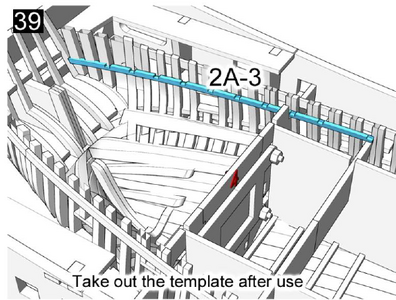
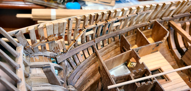
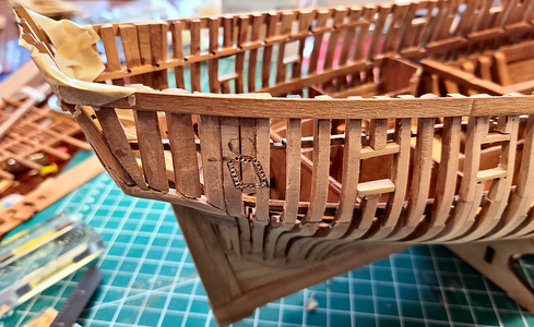
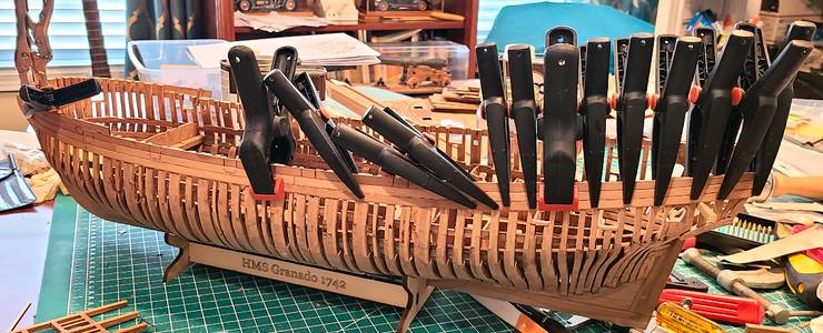
As mentioned previously, I felt I wanted to get the model out of the jig/dock soon, to know what can and cannot be seen through the frames, plan on adding openings for better visibility, etc. But the framework needed to be sturdy enough to withstand removal, and afterwards, to withstand sanding prior to adding more bracing, etc. Since there is a fair amount of internal bracing already added, I felt that, hopefully, adding only the uppermost plank just below the rail would be enough to stabilize it enough prior to removal. So I started adding those planks (row 2-a to 2-d):
1722219635773.png
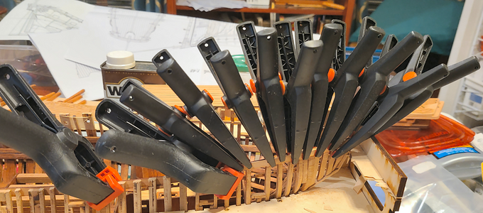
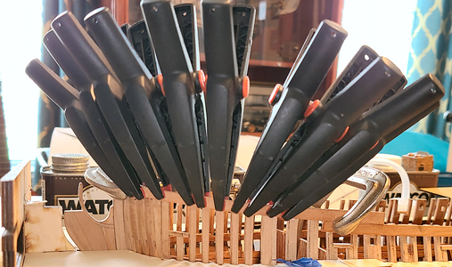
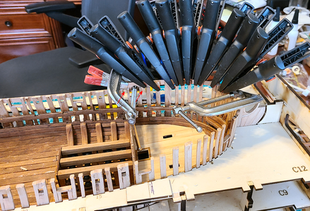
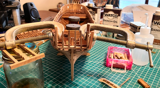
Above is the aftmost plank 2-d in place, glued and clamped, with a temporary piece clamped inside to help align everything. I know that some of my frames may not be well attached to inside bracing, so wanted to be sure here that each and every frame was glued well to the plank. That meant clamping every single frame in place to insure good contact, with the clamp keeping everything aligned properly. I was able to use the top of the frames, sanded previously, to be a good guide as to the elevation and location of the plank.

As you can see, I removed the uppermost level of the jig/dock prior to doing this, to give me more room.

Continuing on to the next plank section, 2-c:
1722219803429.png
I couldn't resist calling my wife in to look: "See honey, how important all those clamps were that I had you buy me for my birthday!" :cool:

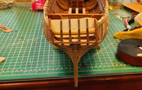
The only plank section requiring any pre-bending at all was at the bow, and I didn't get fancy with bending - just wet them, held in place and let dry. They really didn't need anything done to them, but this put less force on the clamping.
1722219938297.png

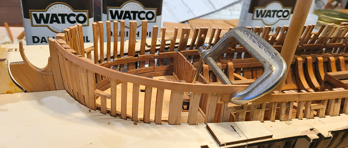
Here I used small C-clamps to tightly secure each end of the upper plank 1-a, to insure no movement, then added the others to keep the frames tight to the planking.
1722219977786.png
Doing the 1-a plank prior to the 1-b plank below it gave me a good line along the frame tops. I left the 1-a plank much longer than needed (as provided), to help align the line with the previous 2-b plank.

A view from the other side shows I added temporary tabs to the top 1-a piece to hold it in line with the 2-b plank, even though it won't be attached to it:
1722220255870.png

This shows the 1-a plank installed, waiting for the 2-a plank to be installed below it:
1722220479667.png

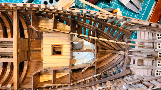
Here the 1-a and 2-a through 2-d planks have been installed:
1722220599809.png
While I felt that the structure was now solid enough to remove from the dock, I did glue in place two of the cross braces over the mortar supports to add some higher side-to-side strength (and yes, I like my weights). I want to add at least some wales before doing TOO much work on the model, but feel/hope that this will allow it to be removed in one piece (and stay in one piece).

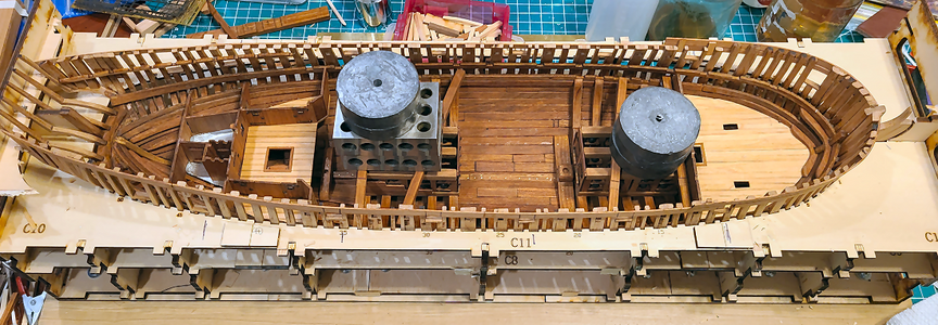
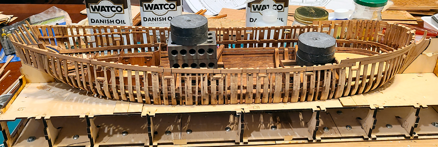
Prior to removal, I wanted to let everything dry overnight, but went ahead and removed the second layer of dock supports:
1722220811049.png
No, this isn't a Watco advertisement, although I wouldn't mind a little reimbursement for buying the products!

1722220864817.png
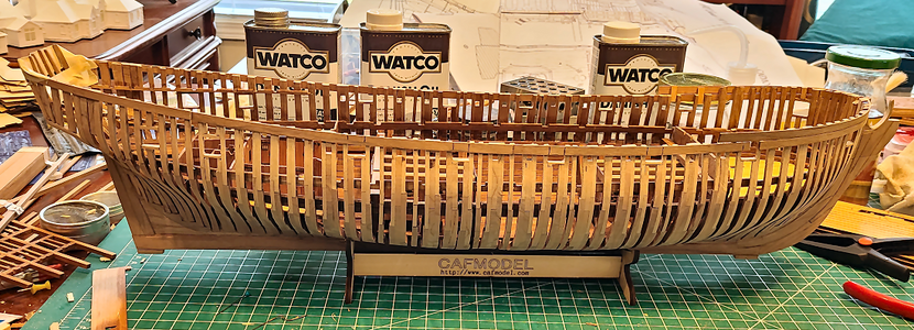
The lines of the vessel start to appear now, with most of it exposed by removing the jig. Getting a bit excited. Well, tomorrow it comes out, and I'll look to further reinforce some areas, notably the stern.

As always, thanks so much for all of your comments, likes and encouragements. I really do appreciate them!
 
Took the hull out to the garage and outside to sand the outer frames. One side to be completely planked, so not sanded that much. The other will be mostly visible, so more sanding required.
1722359115009.png

This is why I wanted to do the outer sanding before going further with the inner detail:
1722359157227.png
1722359168659.png
The hull was quite rigid, and sanding was accomplished with no problems, with this minimum of outer and inner bracing to stabilize it.

After a blow-off with compressed air and vacuuming, it's back to my desk/workbench for work to continue:
1722359250573.png
I've gone in and added the upper sills on the ports that have them, as well as the portion of the frame above them.

For some reason, the corner uprights at the stern, as well as the framing leading up to them, are not canted correctly:
1722359717502.png
I don't know why this happened; it was all glued together while in the jig/dock. I'll have to fix at least some of this canting, although the uprights above the windows will be invisible, being behind other items.

(The spacer below the windows is in place and sanded, but the one above the windows is just there for spacing purposes.) Not sure if I can wet both wall structures near the stern to soften the PVA glue, force them into place, and let the glue harden again, or not. I know if the joints move substantially, they won't be held by the glue very much. Perhaps adding CA glue to the joints after they are in the correct position?
 
Took the hull out to the garage and outside to sand the outer frames. One side to be completely planked, so not sanded that much. The other will be mostly visible, so more sanding required.
View attachment 462008

This is why I wanted to do the outer sanding before going further with the inner detail:
View attachment 462009
View attachment 462010
The hull was quite rigid, and sanding was accomplished with no problems, with this minimum of outer and inner bracing to stabilize it.

After a blow-off with compressed air and vacuuming, it's back to my desk/workbench for work to continue:
View attachment 462011
I've gone in and added the upper sills on the ports that have them, as well as the portion of the frame above them.

For some reason, the corner uprights at the stern, as well as the framing leading up to them, are not canted correctly:
View attachment 462013
I don't know why this happened; it was all glued together while in the jig/dock. I'll have to fix at least some of this canting, although the uprights above the windows will be invisible, being behind other items.

(The spacer below the windows is in place and sanded, but the one above the windows is just there for spacing purposes.) Not sure if I can wet both wall structures near the stern to soften the PVA glue, force them into place, and let the glue harden again, or not. I know if the joints move substantially, they won't be held by the glue very much. Perhaps adding CA glue to the joints after they are in the correct position?
OH Boy. That is weird. I would have thought the jig would have kept it perfectly in symmetry. I am keen to do a POF next and I have a feeling all my frames are going to do thatRedface. These are certainly a big step up from POB models. Some water and heat will loosen the PVA. Cheers Grant
 
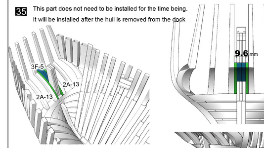
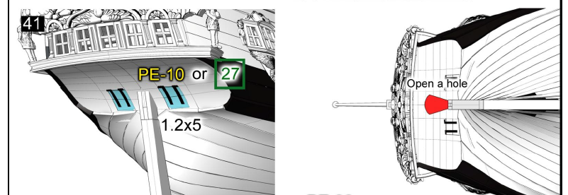
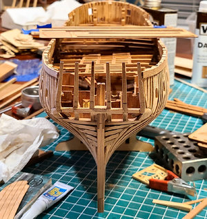
So, I have to add parts 3F-5 (blue) just behind the sternpost:
1722390941234.png
So that later I have to remove it and more to fit the rudder in place?

I was wondering about the opening around the rudder head. I assume this area would be closed off with leather or rubber or something? Probably right where the rudder head enters the hull, and maybe at thee Captain's Day Cabin? How would that be done?

1722391031474.png
 
#3F-5 will be not removed later on, but you have to make an opening for the rudder head

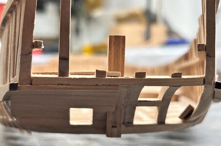
before
IMG_1548.jpg IMG_1549.jpg

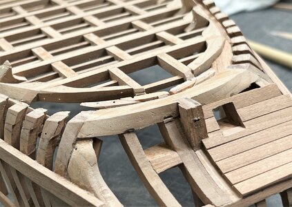
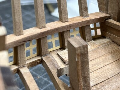
and afterwards
IMG_2485.jpg IMG_3343.jpg

Nevertheless now with my rudder blad I have still to adjust the hole - so I recommend to make this hole really when you install the rudder

Later on the gap between the rudder and the hole will be closed by a canvas, so that no water can go inside
 
This is where I am (or was):
1722634574441.png
That's the first picture I might class as pretty. Things are going to get ugly now.

As mentioned above, the stern pillars at the corners were not angled as they should be (or even close). I used this arrangement, while using water and a bit of heat, to change the angles to close to what they should be:
1722634689943.png
I had to do this before gluing the stern members securely to the sides, or it wouldn't adjust properly. In fact, I probably broke a couple things loose to do this. But eventually, it came out at about the right angle:
1722634774779.png
All I've been wanting to do recently is get more or most of the planking and wales on the port side (which will be fully planked), as well as a minimum of planking and wales on the starboard side, to determine what if any of the frames can be cut away for visibility, while providing strength and stability to the hull structure.

The problem with doing this, as that once done, the stern structure, which holds the windows plus a lot more, will not be able to be moved or adjusted. So, I need to be sure that these things will fit BEFORE I add all the other planking and wales, as well as securely connect the stern structure. THAT, it seems, is a bit of a problem for me. Things must be done waaaaay out of order, causing me to think waaaay ahead, which is a real problem for me. Again.

My process had to start with the stern windows, because the windows actually determine the spacing and angle of the stern posts. They /shouldn't/ IMHO, but they seem to. I took great pains to be sure the spacing and size of these members were EXACTLY as shown in the plans:
1722635382022.png
I assumed (bad me) that the windows, when removed from the wood structure on which they were formed, would fit right between the uprights:
1722635468520.png
Not even close! They were so much wider I assumed they must fit ATOP the uprights, rather than between them. But then the detail columns would not fit between. So I had to narrow each of these, by over 2mm, to fit my structure. Which was very difficult to do, as fragile as they are. I'd already broken one window for the side of the ship. BTW, IMHO, the best way to cut the pane openings in the window is BEFORE removing them from the structure.

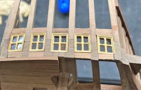
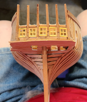
Anyhow, after considerable work on the windows, I was able to fit them into place (sloppily, I now see from the photo):
1722635680802.png
This will all be hopefully sanded and filled to end up looking good. We'll see.

During that process, and when checking ahead, again, in the instructions, I found that the quarterdeck decking actually mounted ON TOP of the horizontal structure just above the windows.
1722635845796.png
Well, the side supports that support the quarterdeck beam (blue below) had been glued in place long ago (unfortunately, with a combination of PVA and CA glues):
1722635955483.png
Like many items, it was to be located by a template that was impossible to install, and which located the height only in a small portion of its length, with no indication of its height near the stern. I guessed wrong on the height. Actually, I measured one drawing, only to find that another drawing showed a very different height. As a result, my quarterdeck would be nowhere near the right height at the stern (and possibly nowhere along its length):
1722636111690.png
This part is so fragile, being cut through half its thickness every half inch or so, that it did not survive. Or it did, but in multiple pieces:
1722636239393.png
Well, one kind of survived. But I realized that with no real indication of height, or distance from anything, for that matter, there was NO WAY this would fit with the Captain's deck partitions. So I decided to remove them entirely, and work out their location while working on the partitions later. And just maybe, if the partition slots don't line up, change how they're supported too.

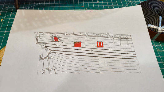
Prior to most of the above, I checked the position of the side "bay" window in on the Captain's deck, by making a template from Goodwin's drawings:
1722648655187.png
It looks to me like the window is higher than it should be, and would be interfering with the quarterdeck supports. But then now I don't know where the quarterdeck supports will end up. I made openings somewhat below what was indicated in the CAF plans, and cut smaller openings. But we'll have to see where they end up when this is all and done. Seems they should have gone aft a bit more, based on the framing.
1722648778311.png
Oh, well, here's hoping tomorrow goes better. And I need to remember to take my photos much further away from my "craftsmanship".
 
This is where I am (or was):
View attachment 462513
That's the first picture I might class as pretty. Things are going to get ugly now.

As mentioned above, the stern pillars at the corners were not angled as they should be (or even close). I used this arrangement, while using water and a bit of heat, to change the angles to close to what they should be:
View attachment 462514
I had to do this before gluing the stern members securely to the sides, or it wouldn't adjust properly. In fact, I probably broke a couple things loose to do this. But eventually, it came out at about the right angle:
View attachment 462515
All I've been wanting to do recently is get more or most of the planking and wales on the port side (which will be fully planked), as well as a minimum of planking and wales on the starboard side, to determine what if any of the frames can be cut away for visibility, while providing strength and stability to the hull structure.

The problem with doing this, as that once done, the stern structure, which holds the windows plus a lot more, will not be able to be moved or adjusted. So, I need to be sure that these things will fit BEFORE I add all the other planking and wales, as well as securely connect the stern structure. THAT, it seems, is a bit of a problem for me. Things must be done waaaaay out of order, causing me to think waaaay ahead, which is a real problem for me. Again.

My process had to start with the stern windows, because the windows actually determine the spacing and angle of the stern posts. They /shouldn't/ IMHO, but they seem to. I took great pains to be sure the spacing and size of these members were EXACTLY as shown in the plans:
View attachment 462521
I assumed (bad me) that the windows, when removed from the wood structure on which they were formed, would fit right between the uprights:
View attachment 462523
Not even close! They were so much wider I assumed they must fit ATOP the uprights, rather than between them. But then the detail columns would not fit between. So I had to narrow each of these, by over 2mm, to fit my structure. Which was very difficult to do, as fragile as they are. I'd already broken one window for the side of the ship. BTW, IMHO, the best way to cut the pane openings in the window is BEFORE removing them from the structure.

Anyhow, after considerable work on the windows, I was able to fit them into place (sloppily, I now see from the photo):
View attachment 462529
This will all be hopefully sanded and filled to end up looking good. We'll see.

During that process, and when checking ahead, again, in the instructions, I found that the quarterdeck decking actually mounted ON TOP of the horizontal structure just above the windows.
View attachment 462530
Well, the side supports that support the quarterdeck beam (blue below) had been glued in place long ago (unfortunately, with a combination of PVA and CA glues):
View attachment 462531
Like many items, it was to be located by a template that was impossible to install, and which located the height only in a small portion of its length, with no indication of its height near the stern. I guessed wrong on the height. Actually, I measured one drawing, only to find that another drawing showed a very different height. As a result, my quarterdeck would be nowhere near the right height at the stern (and possibly nowhere along its length):
View attachment 462532
This part is so fragile, being cut through half its thickness every half inch or so, that it did not survive. Or it did, but in multiple pieces:
View attachment 462533
Well, one kind of survived. But I realized that with no real indication of height, or distance from anything, for that matter, there was NO WAY this would fit with the Captain's deck partitions. So I decided to remove them entirely, and work out their location while working on the partitions later. And just maybe, if the partition slots don't line up, change how they're supported too.

Prior to most of the above, I checked the position of the side "bay" window in on the Captain's deck, by making a template from Goodwin's drawings:
View attachment 462549
It looks to me like the window is higher than it should be, and would be interfering with the quarterdeck supports. But then now I don't know where the quarterdeck supports will end up. I made openings somewhat below what was indicated in the CAF plans, and cut smaller openings. But we'll have to see where they end up when this is all and done. Seems they should have gone aft a bit more, based on the framing.
View attachment 462550
Oh, well, here's hoping tomorrow goes better. And I need to remember to take my photos much further away from my "craftsmanship".
Good morning. Good fix on the stern pillars. I am with Bryan here - there is nothing easy about this build and you have done a great job so far. Cheers Grant
 
Very good progress - and also great final result on your adjustment - seems, that sometimes some stronger forces are necessary
I am sure the old shipwrights did it in a similar way ...... cool
 
I've been working on the port side planking, which I intend to complete, while leaving most of the starboard planking off. Here's where I am:
1722799552827.png
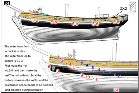
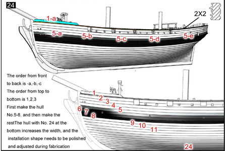
I'm using the following planking diagram in the instructions:
1722801173762.png
I've installed plank rows 1 through 4, shaded in tan, which are all 1# sheets, 1.3mm thick. The next plank is from a thicker 2# sheet, which is 2.1mm thick. I thought this would be the first of the wales strakes, so dyed it black, which may be a mistake. This is why it happened.

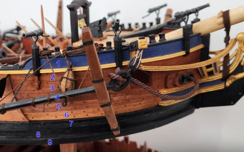
My problem is I'm confused by the strakes, which are "planking" and which are "wales", and therefore black. Looking ahead to strake row #6, it is from 3# sheet which is 3.1mm thick. This is true for rows 6 through 8, and then the remaining strakes 9 through 24 thickness goes back to 1#, 1.3mm thick. This looks right, based on the above diagram and red part numbers (from the instructions), with rows 6-8 being the black wales, and the row 5 being somewhat thicker, a transition, and possibly a strake (black) as well.

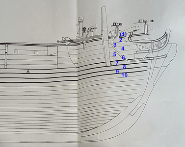
However, the above red numbers are deceiving and wrong, giving the impression that rows 6-8 are, as said above, the thicker, black wales. But my added blue numerals, accurately placed over each strake, show that the bottom-most black strake shown above is actually row 9, not row 8, and therefore not thick and not part of the wales.

Looking at the side drawing of Part No. 3, you can see that the planking row numbers agree with my blue ones above, and not the red ones in the plans (blue numbers added by me, of course):
1722802143909.png
Why is all this a problem? Well, if the planking rows are put on per the plans, the thicker pieces representing the wales will be one full plank higher than shown on the plans. This photo of the completed model shows planking rows agreeing with the drawing:
1722802737981.png
and NOT the laser cut parts included, because rows 6-8 are 3.1mm thick, and row 9 only 1.3mm thick, while row 6 is the same thickness as 7?

So, what am I doing wrong? Why does this not work out with the parts included?
 
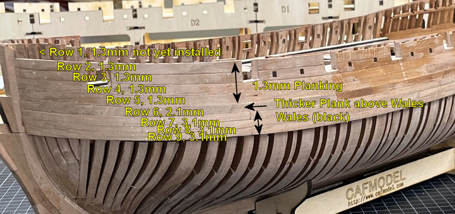
I've been searching and searching trying to figure out the problem. I hope Uwek won't mind if I post a pic from his thread and add notations. This is what he has:
1722823954317.png
(Row 1 only has part 1a, there is no 1b, 1c, etc. - although for some reason there are FOUR parts 1a, rather than 2.)
And, this agrees with the drawings provided by CAF as well as the instructions, but NOT with the planking provided. In my kit, at least, planking Row 5 (5a, 5b, 5c and 5d) is the only row from a 2.1mm thick cherry sheet. And Rows 6-8 are the only rows provided in 3.1mm thick cherry sheet. Row 9 is NOT like shown above, but is instead only 1.3mm thick sheet, so is the first plank below the wales. The parts I have do not make up the above arrangement.

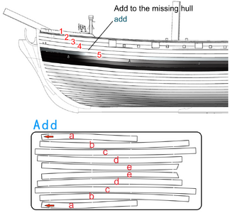
The only way I can see to make this correctly is to insert an additional row of 1.3mm planking, between Row 4 (1.3mm) and Row 5 (2.1mm). Now, since I am only fully planking one side of the model, I think/hope I will have an extra Row 4 that I can use. I believe this may correct the problem, but as no one else has mentioned this during their builds, I'm still wondering if the problem is me. Comments, especially from CAF or builders of this model, would be greatly appreciated!
 
FYI, this is Tom's recommendation:
1722891668609.png
This piece is not included in the kit. He offered to send it to me, and no doubt would to others needing it.

I'd rather not wait, so am adapting the other set of planking row 4 and duplicating it below the existing row 4. Hopefully that will be close enough.
 
Back
Top