A quick question. Does the scroll work on the ship occur in end-grain?for this scroll i made a tiny little chisel from a broked drill bit
View attachment 373368
using the chisel i poked a stop cut along the pattern
View attachment 373369
This is the result
View attachment 373370
back to the diamond burs i am using a cone shape to widen the stop cut.
View attachment 373372
When i have a clean wider channel i will use a smaller diamond bur and refine the scroll
View attachment 373373View attachment 373374
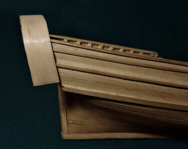
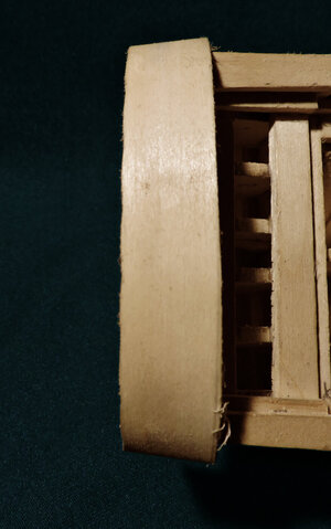
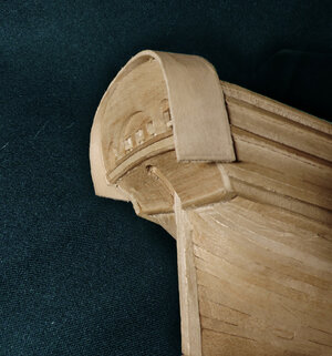
The finished scroll it notches for the cap rail and the cap rail and scroll is glued to the model.
View attachment 373375View attachment 373376
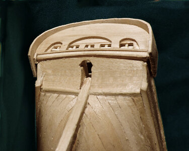
This completes one side of the hull now i have to do it all again for the other side.
a note;
i debated with myself how to handle the stanchions at the stern and the timber heads around the bow. i could have cut a hole through the cap rail for them. This would require cutting 24 perfect square holes in the cap rails and if you mess one up the piece is scrap and you have to start over. The cap rails and the stanchions and timberheads are all painted black so with that in mind i cut them off even with the top of the last plank. My plan is to fabricate the timberheads seperate and glue them to the top of the cap rails, same with the rail stanchions at the stern. I think this way will be way more accurateand a cleaner job, and much faster.
If this were a model showing how the ship was built then yes i would cut the cap rails so the stanchions and timberheads would protrude through. But this is a model showing what the Sultana looked like and not necessarily how it was built.
-

Win a Free Custom Engraved Brass Coin!!!
As a way to introduce our brass coins to the community, we will raffle off a free coin during the month of August. Follow link ABOVE for instructions for entering.
-

PRE-ORDER SHIPS IN SCALE TODAY!
The beloved Ships in Scale Magazine is back and charting a new course for 2026!
Discover new skills, new techniques, and new inspirations in every issue.
NOTE THAT OUR FIRST ISSUE WILL BE JAN/FEB 2026
You are using an out of date browser. It may not display this or other websites correctly.
You should upgrade or use an alternative browser.
You should upgrade or use an alternative browser.
Colonial Schooner Sultana
- Thread starter Dave Stevens (Lumberyard)
- Start date
- Watchers 19
-
- Tags
- 1:48 colonial schooner sultana
- Joined
- Dec 1, 2016
- Messages
- 6,383
- Points
- 728

A quick question. Does the scroll work on the ship occur in end-grain?
the single scroll i cut from a dowel is cut into the end grain. The double scroll is not cut into end grain
- Joined
- Dec 1, 2016
- Messages
- 6,383
- Points
- 728

you may wonder what goes on between postings am i sitting around ignoring the project, or doing yard work and planting our veggie garden, cutting orders, cutting firewood for this winter? well just about all of the above and more.
doing a project like this is a little more complicated because there are no instructions or even a set of plans to follow.
Back in the days when i was working as a graphoc artist it was the policy to never ever delete a previous version of a project. You never know when a client comes in and says "you know what? i like the second version so lets go back to that one" or you made so many changes you can no longer back track.
This is what the Sultans master drawings looks like
in the upper right corner is the original admiralty drawing, below that are the 2 sheet drawings from the Model Expo solid hull kit, the black squares are howard Chapelle's drawings.
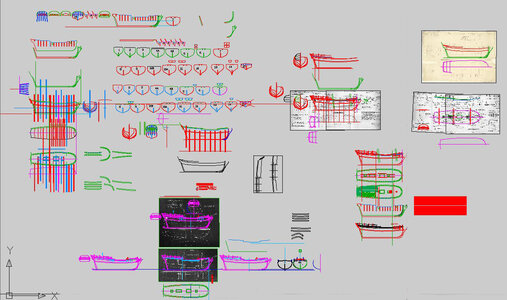
looking close more details begin to show up
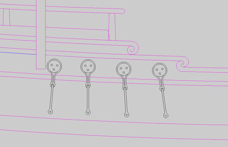
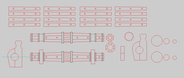
even down to the windlass parts
each source drawing is traced in CAD
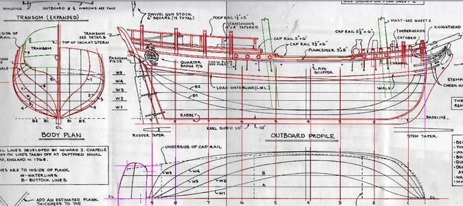
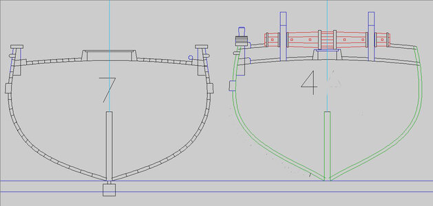
The problems that arise between the 3 drawings for example lets look just at the stern of the Chapelle drawing here all looks OK traced in red to the right is the stern traced from the kit plans
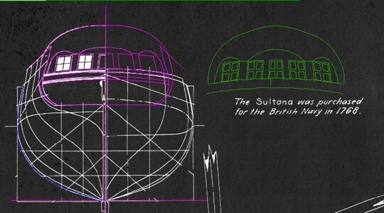
overlay the kit plans on to Chapelle's plans and they are not even close to one another
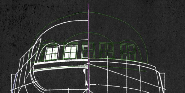
to see a better image
the red is the chapelle stern and the green is the kit overlay them and they are not even close even though all the original plans have been scaled to 1/4 inch= 1 foot.
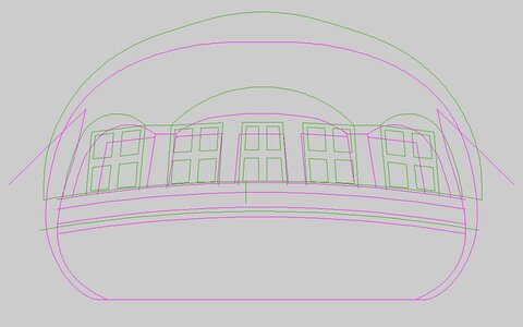
what the final results is you end up with a 4th hybred drawing based on the above 3 drawings. Every line, every dimention or moving anything has a chain reaction and affects something else. This is also why you will see multable drawings in the master because you can back track and see what happened or what will happen if you change something.
everyday work is done on the Sultana project.
doing a project like this is a little more complicated because there are no instructions or even a set of plans to follow.
Back in the days when i was working as a graphoc artist it was the policy to never ever delete a previous version of a project. You never know when a client comes in and says "you know what? i like the second version so lets go back to that one" or you made so many changes you can no longer back track.
This is what the Sultans master drawings looks like
in the upper right corner is the original admiralty drawing, below that are the 2 sheet drawings from the Model Expo solid hull kit, the black squares are howard Chapelle's drawings.

looking close more details begin to show up


even down to the windlass parts

each source drawing is traced in CAD

The problems that arise between the 3 drawings for example lets look just at the stern of the Chapelle drawing here all looks OK traced in red to the right is the stern traced from the kit plans

overlay the kit plans on to Chapelle's plans and they are not even close to one another

to see a better image
the red is the chapelle stern and the green is the kit overlay them and they are not even close even though all the original plans have been scaled to 1/4 inch= 1 foot.

what the final results is you end up with a 4th hybred drawing based on the above 3 drawings. Every line, every dimention or moving anything has a chain reaction and affects something else. This is also why you will see multable drawings in the master because you can back track and see what happened or what will happen if you change something.
everyday work is done on the Sultana project.
- Joined
- Dec 1, 2016
- Messages
- 6,383
- Points
- 728

it's not like i can just flip through the instructions or look at the plans because there are no instructions or plans to look at. When i say built from scratch that goes for not only the model but also the plans and instructions.
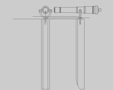
here is the detail drawing in progress for the swivel gun. The gun itself sets in a U shaped bracket that has a spike that extends into a hole at the top of the wood mount. You would think the recoil of the gun would split the post unless there is some sort of iron cap or reinforcement. Would the spike from the U just sit in the hole? are these holes lined with a iron pipe of some sort?
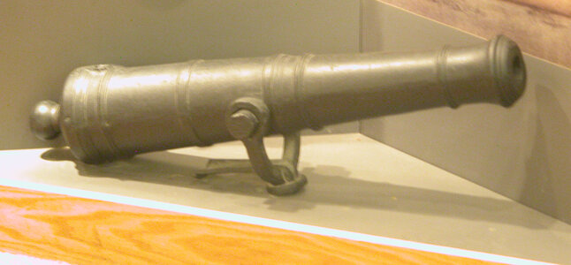
here is a swivel gun in a museum notice there is no spike unless it broke off or removed. Also there is this spoon shaped object what is that?
any information about swivel gun will be greatly appreciated
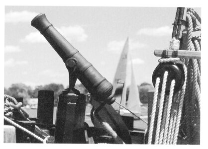
here is an image of the swivel gun on the replica Sultana. i do not see a spike running into the top of the post nor can i figure out what that mount looks like? are those some sort of straps along the side in front and behind the post?
here is the detail drawing in progress for the swivel gun. The gun itself sets in a U shaped bracket that has a spike that extends into a hole at the top of the wood mount. You would think the recoil of the gun would split the post unless there is some sort of iron cap or reinforcement. Would the spike from the U just sit in the hole? are these holes lined with a iron pipe of some sort?

here is a swivel gun in a museum notice there is no spike unless it broke off or removed. Also there is this spoon shaped object what is that?
any information about swivel gun will be greatly appreciated

here is an image of the swivel gun on the replica Sultana. i do not see a spike running into the top of the post nor can i figure out what that mount looks like? are those some sort of straps along the side in front and behind the post?

Last edited:
- Joined
- Dec 1, 2016
- Messages
- 6,383
- Points
- 728

all the cap rails and scrolls are done and i will be back with more posts.
- Joined
- Dec 1, 2016
- Messages
- 6,383
- Points
- 728

All the caprails and scrolls are done except for the cap rail that goes over the stern.
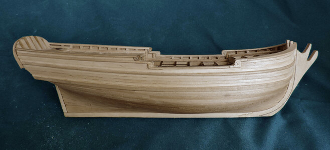
The stern slants back so the top edge is slanted. Before installing the cap rail i sanded down the stern so the cap rail will sit flat at the top.

The first try to bend the cap rail was a total disaster. If you soak the Basswood for an hour it becomes very soft almost like rubber. That was a good thing in one respect but being so soft the pressure from the rubber bans distorted it.
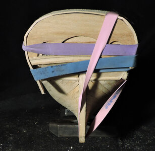
the center wanted to spring up when the sides were bent in resulting in the kinks.
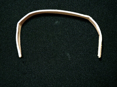
I have done this many times before and i found out it is very difficult to bend and position the cap rail so you get a small overlap along the edge.
The stern is 1/8 thick and the cap rail is 1/4 wide leaving a 1/16 overlap inside and the outside edges. What i do is cut a wide piece twice the width i need.
The problem with bending the cap rail on the stern is the stern is only 1/8 wide and trying to bend a piece 1/2 wide resulted in all kinds of twists and bends.
to get a nice flat even bend exactly the shape of the stern i traced the stern shape and cut a 1 inch wide pattern piece to bend the cap rail on.
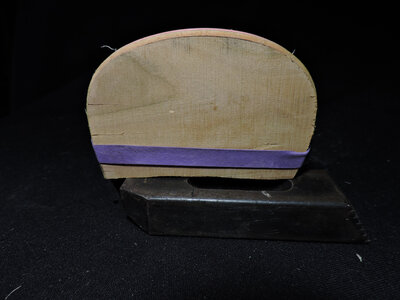
The Basswood is soft when soaking wet and took the arched bend with no problem.
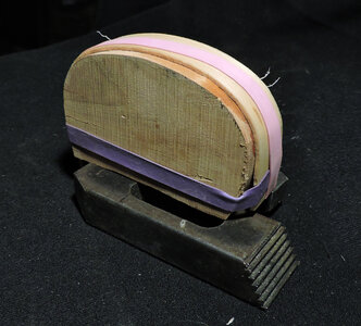
To make sure the cap rail remained flat and to prevent the center from wanting to spring up i used a second rubber band over the pattern.

The rubber bands are from the local grocery store and are used in the produce department to hold bundles of vegetables together. They are wide and quite strong. So that kept the cap rail from cupping, warping or twisting.
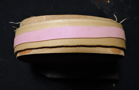
What a difference form trying to bend the cap rail over a thin stern and bending it over a form the shape of the stern. I now have a perfect fit.
The bend would be to extreme for any type of hardwood like Cherry or Maple. Willow, Basswood and maybe Poplar will take the bend.
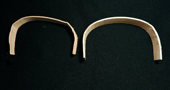

The stern slants back so the top edge is slanted. Before installing the cap rail i sanded down the stern so the cap rail will sit flat at the top.

The first try to bend the cap rail was a total disaster. If you soak the Basswood for an hour it becomes very soft almost like rubber. That was a good thing in one respect but being so soft the pressure from the rubber bans distorted it.

the center wanted to spring up when the sides were bent in resulting in the kinks.

I have done this many times before and i found out it is very difficult to bend and position the cap rail so you get a small overlap along the edge.
The stern is 1/8 thick and the cap rail is 1/4 wide leaving a 1/16 overlap inside and the outside edges. What i do is cut a wide piece twice the width i need.
The problem with bending the cap rail on the stern is the stern is only 1/8 wide and trying to bend a piece 1/2 wide resulted in all kinds of twists and bends.
to get a nice flat even bend exactly the shape of the stern i traced the stern shape and cut a 1 inch wide pattern piece to bend the cap rail on.

The Basswood is soft when soaking wet and took the arched bend with no problem.

To make sure the cap rail remained flat and to prevent the center from wanting to spring up i used a second rubber band over the pattern.

The rubber bands are from the local grocery store and are used in the produce department to hold bundles of vegetables together. They are wide and quite strong. So that kept the cap rail from cupping, warping or twisting.

What a difference form trying to bend the cap rail over a thin stern and bending it over a form the shape of the stern. I now have a perfect fit.
The bend would be to extreme for any type of hardwood like Cherry or Maple. Willow, Basswood and maybe Poplar will take the bend.

- Joined
- Dec 1, 2016
- Messages
- 6,383
- Points
- 728

now that i have the stern cap rail bent i will glue it to the stern.
you need to make sure the top center of the cap rail is parallel to the keel so it does not slope to the front or back. In order to do this place the cap rail on a flat surface and prop up the bow so the keel is parallel to the surface.
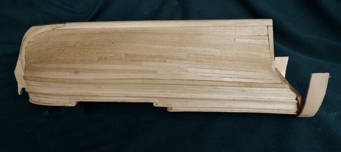
i only applied glue to the center of the stern leaving the ends free.
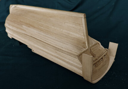
When i bent the cap rail around the form it bent square to the form, so the cap rail will not fit the stern because the stern slants. If i glue to caprail to match the stern the top surface will slant like the stern.
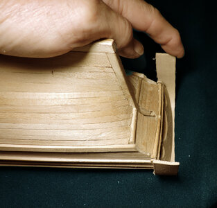
The reason i made the cap rail so wide is so it will be wide enough to conform to the slant of the sten. By putting a finger on the outer corner Basswood has enough give you can pull the end back to cover the sides of the stern. If i cut the cap rail to the finish width of a 1/4 inch that would require to much of a bend backwards and either the cap rail will buckle or break. A wide pieces takes far less stress and pressure to get the rail centered on the siide of the stern.
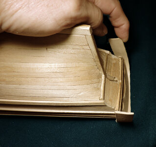
you need to make sure the top center of the cap rail is parallel to the keel so it does not slope to the front or back. In order to do this place the cap rail on a flat surface and prop up the bow so the keel is parallel to the surface.

i only applied glue to the center of the stern leaving the ends free.

When i bent the cap rail around the form it bent square to the form, so the cap rail will not fit the stern because the stern slants. If i glue to caprail to match the stern the top surface will slant like the stern.

The reason i made the cap rail so wide is so it will be wide enough to conform to the slant of the sten. By putting a finger on the outer corner Basswood has enough give you can pull the end back to cover the sides of the stern. If i cut the cap rail to the finish width of a 1/4 inch that would require to much of a bend backwards and either the cap rail will buckle or break. A wide pieces takes far less stress and pressure to get the rail centered on the siide of the stern.

- Joined
- Dec 1, 2016
- Messages
- 6,383
- Points
- 728

- Joined
- Dec 1, 2016
- Messages
- 6,383
- Points
- 728

looking at the inside of the stern you can see there is plenty of material over hanging the stern timbers inside and out.
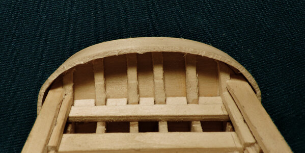
With the cap rail now glued down it is time to shape it starting along the outer edge of the stern and sand down the edge until you have a nice even overlap.

now the shape of the cap rail is established mark the width. I used an Exacto blade and shaved down the edge until i got close to the line and sanded the cap rail to the final shape.
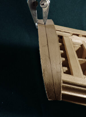
The final results
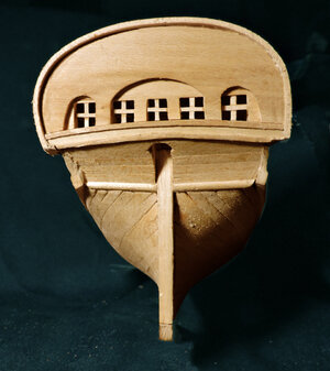
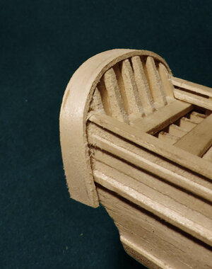

With the cap rail now glued down it is time to shape it starting along the outer edge of the stern and sand down the edge until you have a nice even overlap.

now the shape of the cap rail is established mark the width. I used an Exacto blade and shaved down the edge until i got close to the line and sanded the cap rail to the final shape.

The final results


- Joined
- Dec 1, 2016
- Messages
- 6,383
- Points
- 728

- Joined
- Dec 1, 2016
- Messages
- 6,383
- Points
- 728

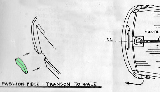
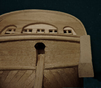
the side molding butts against the front edge of the fashion piece and the lower stern planking butts against the side of the fashion piece. The fashion piece also extends the cap rail and ends at the wale.
To start i drew a curved line from the forward lower corner of the cap rail down to the wale. Because the planking is Basswood it cut easy with an Exacto blade.
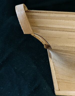
Fitting the fashion piece takes shaping one side at a time. First to cut is the top that will sit against the bottom of the cap rail then the arc of the lower stern and the forward arc.
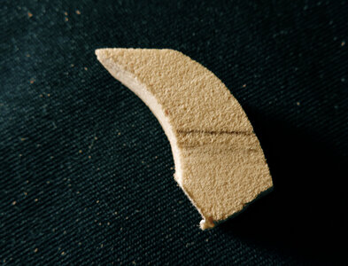
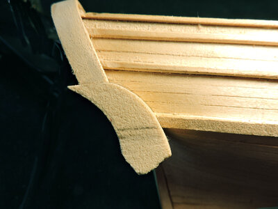
To start i drew a curved line from the forward lower corner of the cap rail down to the wale. Because the planking is Basswood it cut easy with an Exacto blade.

Fitting the fashion piece takes shaping one side at a time. First to cut is the top that will sit against the bottom of the cap rail then the arc of the lower stern and the forward arc.


- Joined
- Dec 1, 2016
- Messages
- 6,383
- Points
- 728

the third arc to cut is the edge of the lower stern planking
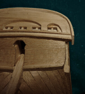
The working piece is thicker than the finished piece to allow for the arc to fit against the stern planking
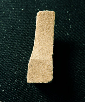
when finished the fashion piece is still pretty much a block. At this stage of the fit you should have 3 arc cut and fit.
1 is against the lower stern planking
2 against the side planking
3 the arc of the stern

The working piece is thicker than the finished piece to allow for the arc to fit against the stern planking

when finished the fashion piece is still pretty much a block. At this stage of the fit you should have 3 arc cut and fit.
1 is against the lower stern planking
2 against the side planking
3 the arc of the stern

- Joined
- Dec 1, 2016
- Messages
- 6,383
- Points
- 728

With the fashion block fitting the model it can now be shaped. From the side trim the bottom to the lower edge of the wale, the 2 arcs were done at the start.
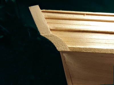
The final shaping was done when the fashion timber was installed on the model. This shaping is the outer face which starts at the bottom of the cap rail and tappers to the wale.
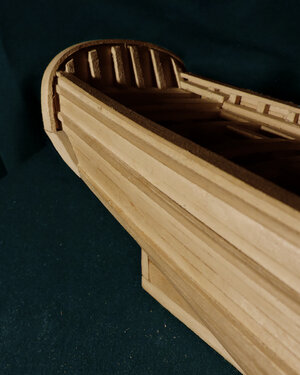
looking from the stern you can see the tapper and how the fashion piece finishes off the corner of the stern.
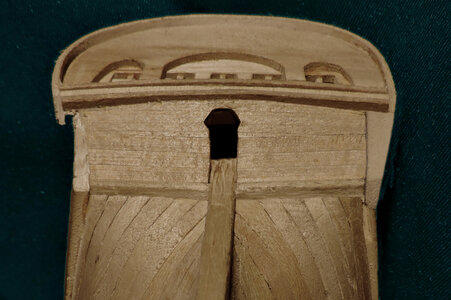
At the stern the fashion piece creates an overlap of the planking like the moldings and cap rail.
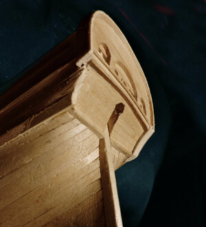
Keep in mind when you cut the first 2 arcs make sure you leave enough material for the overlap at the stern. You can see the point of the fashion piece extending beyond the cap rail. This arc is just a rough starting point. One the faship piece was on the model the arc was refined to the shape of the lower planking.
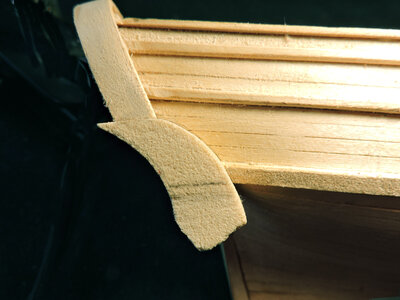

The final shaping was done when the fashion timber was installed on the model. This shaping is the outer face which starts at the bottom of the cap rail and tappers to the wale.

looking from the stern you can see the tapper and how the fashion piece finishes off the corner of the stern.

At the stern the fashion piece creates an overlap of the planking like the moldings and cap rail.

Keep in mind when you cut the first 2 arcs make sure you leave enough material for the overlap at the stern. You can see the point of the fashion piece extending beyond the cap rail. This arc is just a rough starting point. One the faship piece was on the model the arc was refined to the shape of the lower planking.

- Joined
- Dec 1, 2016
- Messages
- 6,383
- Points
- 728

one fashion piece done and one to go before i start on the decks so stay tuned the decks are coming soon.
- Joined
- Dec 1, 2016
- Messages
- 6,383
- Points
- 728

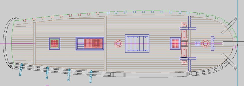
moving on to the decks, being the designer, draftsman and builder i started with concept and drawing the deck layout.
the deck planks are 6 inches wide. On real decks they are not really a "plank" decks are closer to being a square almost as thick as they are wide. This was done because wide thin planks tend to cup. Narrow is better than wide. When you get to the edge along the hull your faced with the planks running to a point. like you see on the stern decks. On some decks the planking followed the shape of the hull and a king plank was used down the center. What i thought of doing was using a wide plank at the tiller deck and the main deck just to see if it would work and avoid running the planks to a point. Looking at the stern deck that last plank is very narrow and runs to a point that would be hard to nail down.
At this point the drawing is more a concept and i will have make adjustments. The wide plank on the main deck seems logical but correct? i am not sure.

- Joined
- Dec 1, 2016
- Messages
- 6,383
- Points
- 728

looking at a real deck you can see the deck planks curve i do not know if laying a deck differed from builder to builder and from yard to yard but it does avoid the edge planks from running to a point.
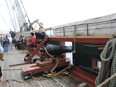
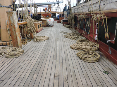
even running the planks on a curve along the edge of the hull you still reach a point where the plank come to a point. Here you see how that is delt with at the center of the deck.
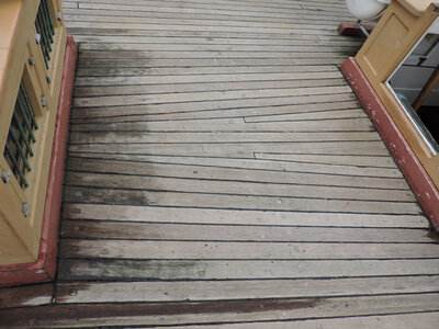
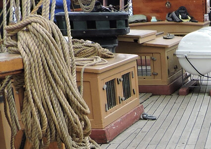
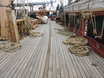
before i start the decking on the Sultana i will draw up different layouts


even running the planks on a curve along the edge of the hull you still reach a point where the plank come to a point. Here you see how that is delt with at the center of the deck.


before i start the decking on the Sultana i will draw up different layouts
- Joined
- Dec 1, 2016
- Messages
- 6,383
- Points
- 728

the last model i built i did run the planking along the side and curved it. The decking came out looking good and it was not difficult bending the planks edgewise
so i will try different ways first or do drawing for curving the deck planks and running the planks straight and leave it up to the builder to choose which wy they want to go.
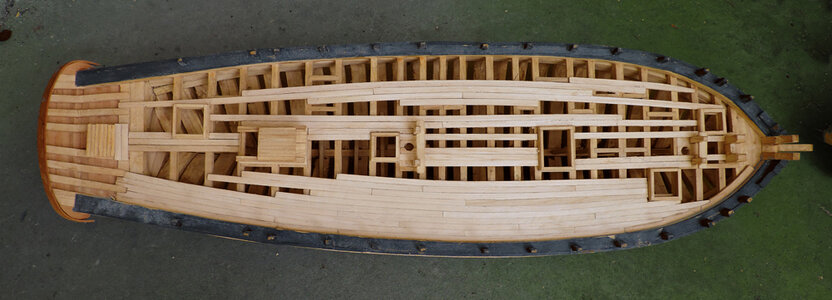
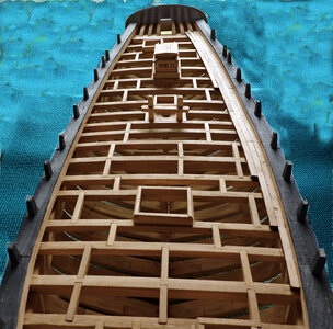
so i will try different ways first or do drawing for curving the deck planks and running the planks straight and leave it up to the builder to choose which wy they want to go.


- Joined
- Dec 1, 2016
- Messages
- 6,383
- Points
- 728

Starting at the stern
first to set in the rudder frame
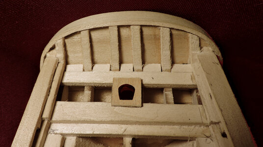
starting at the edge of the rudder frame as i reached the waterway i sightly tapered the last two planks and slipped a piece of cardboard under the last plank to get a pattern for the last plank.
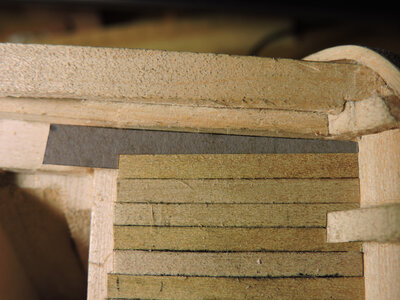
I ran the planks at random lengths off the edge, At this point the job looks sloppy and that's because i used China Marker for the caulking. It is a soft waxy marker and has a slight stickiness.
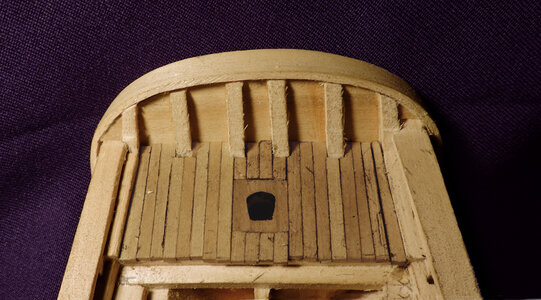
The edge of the deck has a nose piece and i figured it would be easier to cut the ends off the planking rather than trying to fit each one between the nose and the stern.
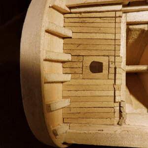
cutting off the ends worked out and i fit the nose piece.
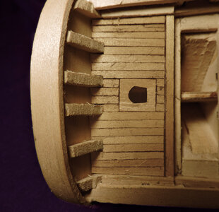
with a little sanding and clean up it came out ok. i like the China Marker because it is soft and molds to the edges of the planking finishing in a fine line. I found out you have to mark all the plank edges. Just marking one edge to a clean edge makes a thin line. When both edges have marker on them together they make a caulking line clost to scale.
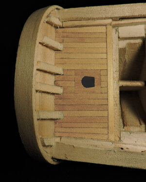
next deck has hatch coaming to make, so thats next
first to set in the rudder frame

starting at the edge of the rudder frame as i reached the waterway i sightly tapered the last two planks and slipped a piece of cardboard under the last plank to get a pattern for the last plank.

I ran the planks at random lengths off the edge, At this point the job looks sloppy and that's because i used China Marker for the caulking. It is a soft waxy marker and has a slight stickiness.

The edge of the deck has a nose piece and i figured it would be easier to cut the ends off the planking rather than trying to fit each one between the nose and the stern.

cutting off the ends worked out and i fit the nose piece.

with a little sanding and clean up it came out ok. i like the China Marker because it is soft and molds to the edges of the planking finishing in a fine line. I found out you have to mark all the plank edges. Just marking one edge to a clean edge makes a thin line. When both edges have marker on them together they make a caulking line clost to scale.

next deck has hatch coaming to make, so thats next
- Joined
- Dec 1, 2016
- Messages
- 6,383
- Points
- 728

Before building the quarter deck the two hatch coamings are made.
the coamings are made from 1/8 x 14 stock, tools i use are a razor saw, mini vice and a razor blade
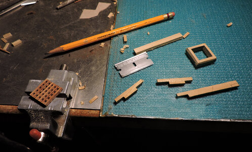
Model builds think they need a mill to get perfect fitting joinery but all i use is a vice and razor blade
using a razor blade i slice off thin pieces from the joint being cut.
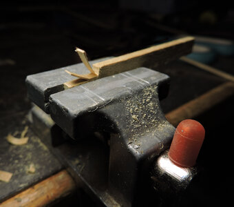
As i approach the top of the vice i take thin slices
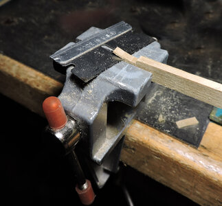
until i reach the top of thie vice the last cut will give me a flat surface everytime.

after cutting one end i clamp it another pieces and make a score line along the top of the joint. then with the razor saw i cut the vertical cuts. This insures both ends are the same.
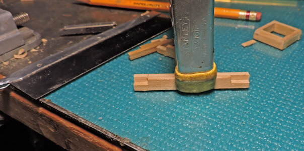
now i have a vertical cut as well as a sharp score line
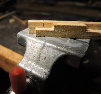
place the piece in the vice so the score line is at the top of the vice. Then shave it down with a razor blade.
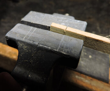
the coamings are made from 1/8 x 14 stock, tools i use are a razor saw, mini vice and a razor blade

Model builds think they need a mill to get perfect fitting joinery but all i use is a vice and razor blade
using a razor blade i slice off thin pieces from the joint being cut.

As i approach the top of the vice i take thin slices

until i reach the top of thie vice the last cut will give me a flat surface everytime.

after cutting one end i clamp it another pieces and make a score line along the top of the joint. then with the razor saw i cut the vertical cuts. This insures both ends are the same.

now i have a vertical cut as well as a sharp score line

place the piece in the vice so the score line is at the top of the vice. Then shave it down with a razor blade.

Last edited:
- Joined
- Dec 1, 2016
- Messages
- 6,383
- Points
- 728

Depending on how accurate you want to build a common mistake is to assemble the corners at a 45 degree angle. Actually the corners are joined by a lap joint.
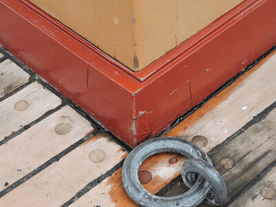
if you want to reaaly get accurate the faces are cut on an angle. Cutting the faces on an angle would not work with the vice and slice method, so i am sticking with the flat face joint.
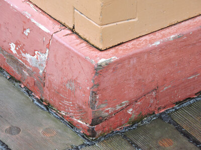
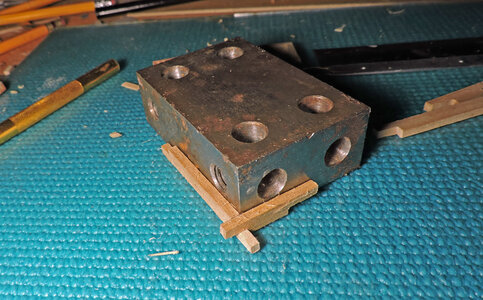
assembling the coamings i use a machinest block and square up one corner. Then i do the same with the other two sides ending up wth two L shaped pieces
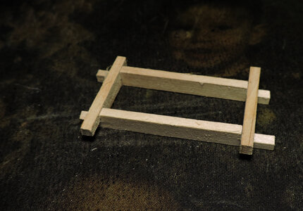
when you assemble the two L pieces they will automatically square up as long as the two end pieces are the sames as well as the two sides.
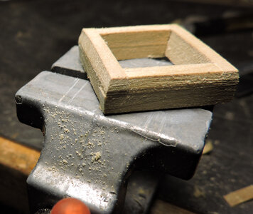
the last step is to bevel the top side. To get an even bevel i used a tiny bit of the china marked and rubbed it on the side. As you sand the bevel it leaves a clean sharp edge to follow. The side in front needs more sanding if you look close at the corner in the darker area you can see a fine line running along the side and a little more darker area above the line to remove.
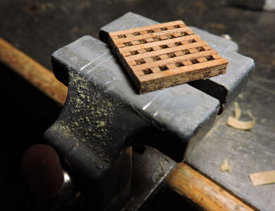
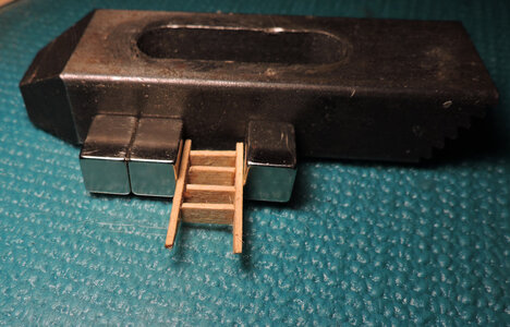
a couple extras are the ladder and gratings. As for the ladder it is easy to build from scrap deck planking, the gratings are laser cut so all i did was asseble the grating.

if you want to reaaly get accurate the faces are cut on an angle. Cutting the faces on an angle would not work with the vice and slice method, so i am sticking with the flat face joint.

assembling the coamings i use a machinest block and square up one corner. Then i do the same with the other two sides ending up wth two L shaped pieces

when you assemble the two L pieces they will automatically square up as long as the two end pieces are the sames as well as the two sides.

the last step is to bevel the top side. To get an even bevel i used a tiny bit of the china marked and rubbed it on the side. As you sand the bevel it leaves a clean sharp edge to follow. The side in front needs more sanding if you look close at the corner in the darker area you can see a fine line running along the side and a little more darker area above the line to remove.

a couple extras are the ladder and gratings. As for the ladder it is easy to build from scrap deck planking, the gratings are laser cut so all i did was asseble the grating.


Last edited:


