Colonial Schooner Sultana

First i gave the deck beams a sanding to insure i have a flat surface to lay the deck on. When the two coamings are finished they are glued to the deck. The ends of the planking butt against the bull nose piece so that also has to go in. On the last deck i ran the planking off the edge and cut the ends to install the bull nose piece. This time i installed the bull nose pieces first. The bull nose of the deck extends slightly over the break in the deck so the wall at the break of the deck has to be installed before the decking. This is an easy task of just gluing virtical planks on to the face of the plywood.

deck19.jpg
 
Last edited:
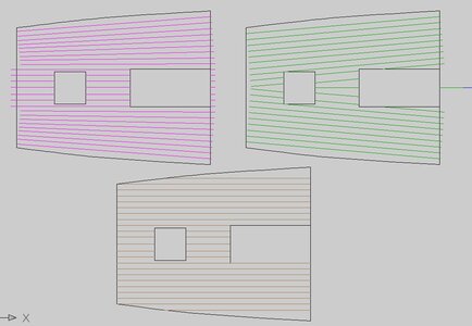
the deck i used CAD and drew up a few ideas for laying the deck to see what happens. The idea is to eliminate the edge planks from coming to a sharp point.

the red draw the planks are tappered and that is a lot of work to get the tapper just right.

the green drawing i started to run the planks parallel to the waterways, that eliminated the planks from coming to a point along the side but they ended up in the center. I have seen decks done this way.

the brown drawing is the most logical and it did end up with the last two planks ending in a point. so that is what i went with.

drawing.JPG
 
Hey Dave ! I think it is really great that you are tali g the time to explain the details of how you do things ! It is very helpful to beginners and even the experienced builders pick up some tips here and there !
 
Hey Dave ! I think it is really great that you are tali g the time to explain the details of how you do things ! It is very helpful to beginners and even the experienced builders pick up some tips here and there !

Thank you for the comment.
I see a lot of build logs that skip over the "how to" and jump from next i will install the deck and the next image is a finished deck. i try to fill in how i got from point A to point B.
 
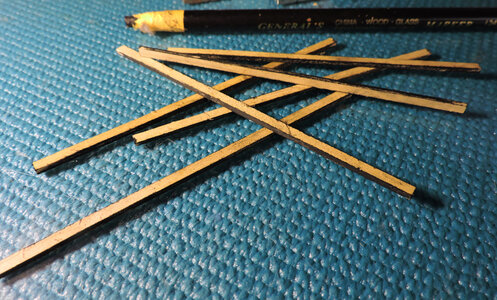
Starting the deck i used my China marker to blacked the edges of the planks, a messy job because the marker gets on your fingers from holding the strips.
deck23.jpg

No need to go through the planking job plank by plank. Cutting the planks to fit between the break in the deck aft and the bull nose was no problem cutting the planking to fit nice. The one issue with using a China marker, it is messy it gets on you fingers from handling the planks. It is soft, waxy and sticky and gets on everything you touch. When all the planks are in place it looks bad dirty and messy.
Notice along the waterway there are no planks that come to a point like they did on the CAD drawing. Actually i did not plan for the decking to work out that way. Drawing in CAD and making the planks 1/8 wide they are exactly 1/8 wide. When in reality the deck planking is slightly wider and the drawing goes from line to line, on the deck there is the gap of caulking between each plank.

Drawings by hand have a + or - in CAD there is no + or - and they are exact. Building from a plan there will always be a need for adjustments, it is called the hand of man factor or the creeping measurement. So like the deck it was sheer chance it worked out the way it did. As i approached the waterway i saw i could fit the last plank if i used a wider plank and tappered it.

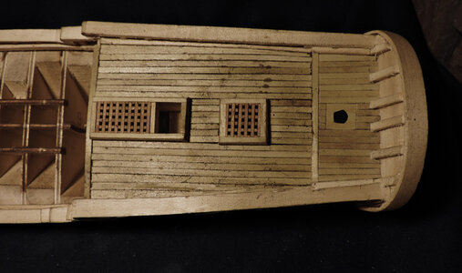
Getting back to a dirty deck lucky China marker does not smear it is either there or not so clean-up is no big deal.
deck20.jpg

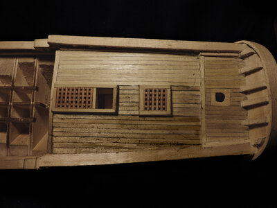
i did 1/2 the deck to show the clean compared to the uncleaned.
deck21.jpg

The deck area is kind of small and a block of wood with sandpaper was to big. Finishing a deck i like to scrape it rather than sand it. The end of a file has a edge that is not supper sharp but sharp enough to scrape clean the deck. I have used old files and tool steel and ground an edge to use as a scraper, you do not want to sharp of an edge because it will cut into the wood and not scrape it. Scraping the deck works fine in open areas but between the hatches i will have to sand.
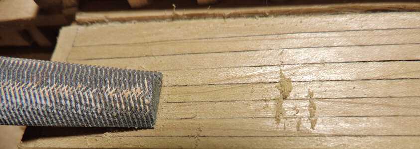
deck22.jpg

i still have to add the binnacle but that will be one of the last pieces to add to the model. I learned the hard way fine details are prone to get damaged from handling the model while under construction.
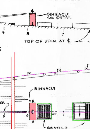
binnacle.jpg
 
Last edited:
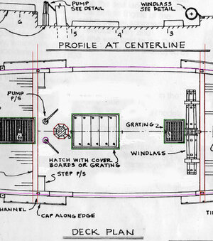
and now for the main deck so lets take a look at what has to be done.
We are looking at the original drawing provided in the kit which gives us an idea of what is needed.

main deck plan.JPG

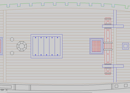
This is the CAD drawing for the main deck. I left the last plank along the waterway open, i learned from the last deck you never know how it will turn out. In CAD it is a double wide plank at the center and tappers at the ends. Talk about scale it is quite a large piece of wood, the real deck is 3 inches thick and at the widest point the plank is 10 inches wide. That is possible in real life.
main deck.JPG

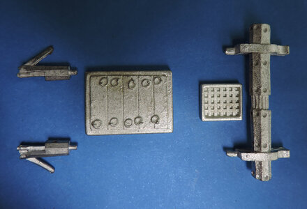
These are the original cast fittings from the kit. We already built 2 hatches so the next two should be no problem. If you built the model to this point making the pumps out of wood should be easy.

cast parts.jpg

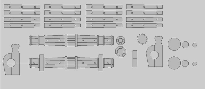
As for the windlass, well that is another thing making it from scratch so first i designed it in CAD then layed out the parts for a laser cutting file. i will be assembling the windlass rather than cutting out all the parts by hand and building it from scratch..

windlass1.jpg
 
Last edited:
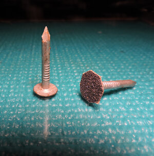
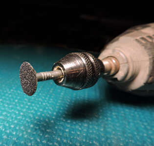
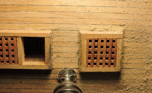
Between the hatches is a tight space so i needed to come up with a small sanding disk. What i used is a roofing nail that has a big head. Using double sided tape i stuck a piece of 120 grit sandpaper to the nail head. double sided tape comes in a range of thicknesses, what i am using is a thicker tape. The reason for thicker tape is to create a softer pad under the sanding disk. If you glued the sanding disk directly on the nail head when sanding it tends to burn the wood or gouge the deck. Thicked tape or boubling up the tape makes for a softer sanding and less likely to cut gouges.

deck24.jpgdeck25.jpg

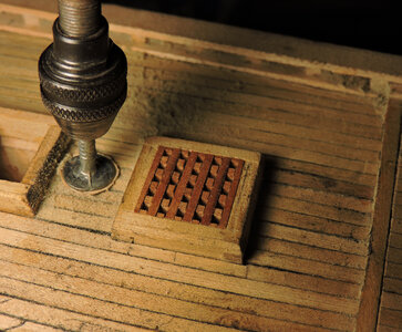
nowi can sand between the hatches. A couple pointers make the sanding disk larger than the nail head because if you make it the same size when you go along the waterway or coamings the edge will cut into the wood. Leaving extra sandpaper around the edge creates a soft buffer zone so you don't cut into the sides of the coamings. Use a finer grit from 120 to 240 because the disk will sand fast and a rough grit will gouge the deck.

deck26.jpgdeck27.jpg
 
Last edited:
i need to do some work and finish the last deck, make the two hatches and get the windlass laser cut, Then i will lay down the main deck. There is no need to repeat the process. We know how to cut and assemble hatches and we know the process of using China marker and building a deck.

When i get the parts cut for the windlass i will do a step by step assembly. It is the 1st prototype drawing and build so hopefully it works out the first time.

d9tb60g-545a9461-14ff-486a-8e5d-3b0a429e63bb.jpg
 
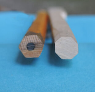
on the original plans the pump has 8 sides but when the punp is set on the deck the 8 sides are so small it looks round. So i decided to make the pump with 6 sides so you can actually see the different sides.

pump 2.jpg

a simple way to make a 6 sided pump is to use a pencil which has 6 sides and is actually the right size for a 1:48 scale pump and has a pre drilled hole.

pump 3.jpg
 
Last edited:
But if you want to make a pump with 8 sides the first problem is how do you make 8 equal sides? I did the math starting with a 1/4 inch square piece of wood.

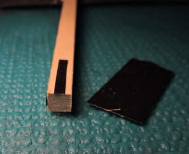
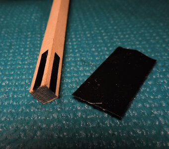
knowing the measurement of the sides i use electrical tape and cut a strip to the correct width. I use electrical tape because it cuts clean and sharp and it is black so the edge shows up.

pump 4.jpg

cutting the strip in 4 pieces each one is stuck in the center on each side. i did eye ball the the placement. you can't be that far off.

pump 5.jpg

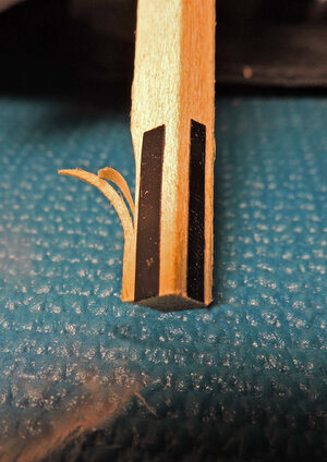
using Basswood it slices very easy

pump 7.jpg

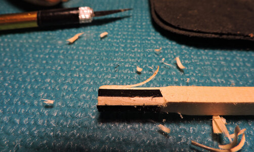
the idea here is to take thin slices off the corners using the edge of the tape as a guide. I used an Exacto blade but a file or sandpaper will also work.

pump 6.jpg

what is nice about this is if you goof it up just cut off the end of the 1/4 inch stick and try it again. It may not turn out perfect but it will be so close you can not tell if one side is slightly bigger or smaller.
 
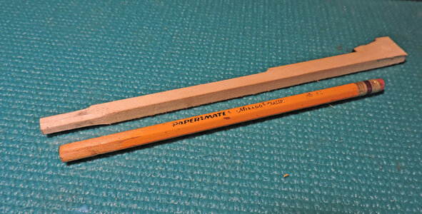
i went with the 6 sided pencil, first using a razor blade i scrapped off the yellow paint and cut a piece off the end to the proper length.
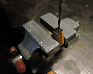
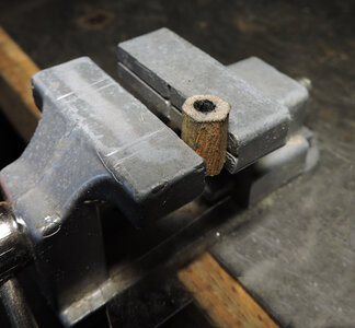
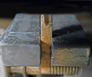
clamping the piece in a vice i hand drilled out the lead which is actually graphite.

pump 8.jpg

this gave me a starter hole dead center. By the way the graphite is messy and gets on the outside of the piece.

pump 9.jpg

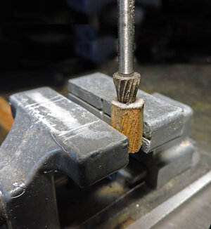
the hole in the pencil is a little small so i reamed it out a bit. Depending on how close you want to get to the edge you can ream or drill out the hole. Even if you split the the piece you can make a heck of a lot of pumps from one pencil.

pump 10.jpg
 
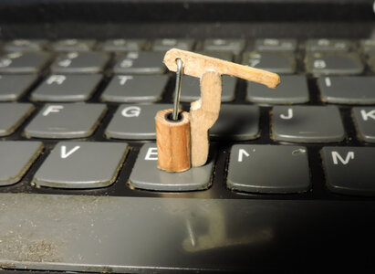
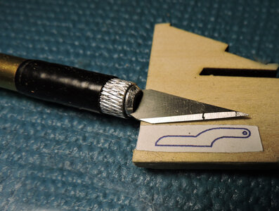
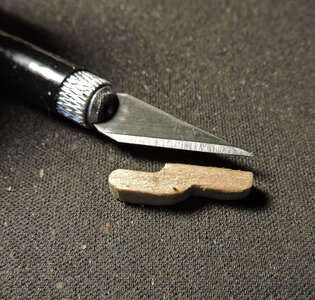
This pump is small and it would seem intimidating to make such little parts. to be honest it took maybe half and hour to make the pump from start to finish with no make overs. Using the drawing on the CAD plans i pasted the bracket on a piece of 1/8 thich Basswood. Once again Basswood is soft and easy to cut so i cut the piece out with square corners and finished it off with a file to get the rounded corners.

pump 11.jpg

pump 12.jpg

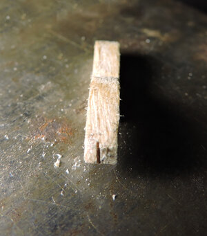
The next step using the Exacto knife i made a shallow cut on the top end. i did this as a guild at the center of the width.

pump 13.jpg

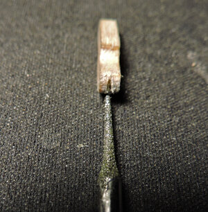
using the smallest diamond bit i filed the cut a little wider manking sure i did not take more off one side than the other. At this point all i want is a V grove as a guide. I did this by hand to maintain better control. if i uses the bit in the dremel it would cut so fast before i can react to correct any wondering.

pump 14.jpg

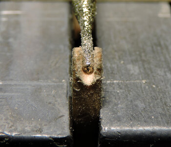
the final cut is a wider diamond bit which i did put in the Dremel and the cut was almost instant. But that is the reason for the V grove acting as a guild. With a steady hand you can skip the first 2 steps and just cut the grove.
the wood looks fuzzy because you are seeing it really closeup, in real life it looks clean and smooth.

pump 15.jpg

the grove is done and the sides are still intact, delicate but intact.

pump 16.jpg
 
Last edited:
The next piece is the handle

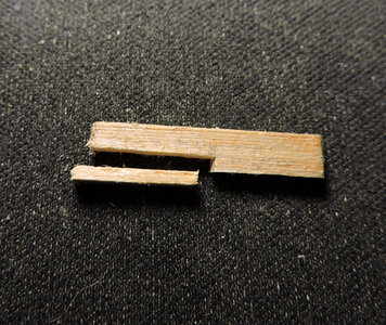
starting with a strip of Basswood 1/8 wide and 1/32 thick i cut a piece off the end to the correct length for the handle and cut away a piece for the handle part. All i am using is a single edge razor blade, nothing fancy.

pump 17.jpg

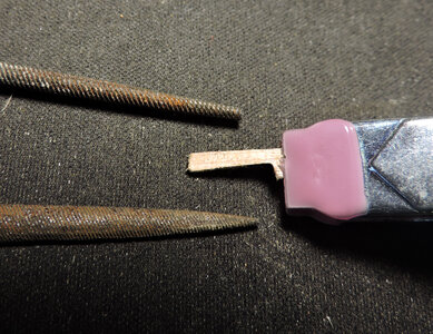
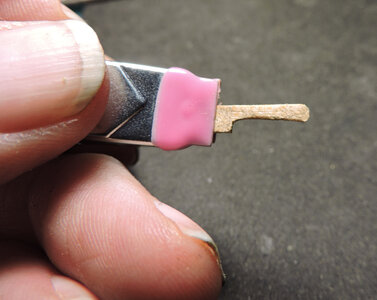
the piece is quite small and hard to hold on to while working it. what i uses is a spring clamp to hold the piece the use files to shape the handle. I found myself using needle files a lot so if you intend on doing a build like this i suggest getting a set if you don't lready have one.

pump 18.jpg

And the final shape of the handle. You can see judging from my fingers this piece is small.

i have noticed in building these models the wow factor come from the small details. You first look at the model as a whole then as your looking you see smaller and smaller details and that is what draws you in. The trick to the illusion is keeping the details in scale or as close to scale as you can get. What you want to do is create details that get so small they create a vanishing point. What disrupts the illusion is out of scale details like trying to add planking spikes or treenails that are so out of scale they jump out and that is all you see. Better to leave off out of scale details and leave it up to the imagination of the viewer.

pump 19.jpg

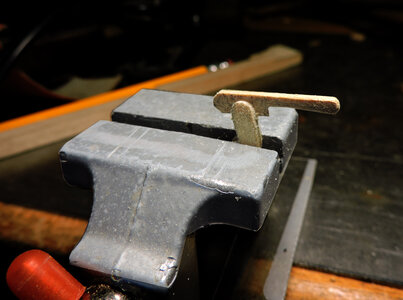
The handle placed in the grove. there would be a pivit pin that goes through the brace and handle. you can just make a pin prick and color it in or once you glue the handle in place drill a tiny hole and insert a pin. builder choice

pump 20.jpg

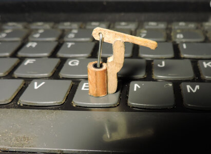
finished! a scratch build pump that is to scale, looks better than a cast metal fitting and you can show it off to friends and family and say i built this.


pump 1.jpg
 
Hello Dave,

thank you very much for your great postings of your construction and modelling Sultana.

I will gladly follow your posts, because I have ordered the Sultana kit from Model Expo and two books about Sultana a few days ago.
Your idea of making your own plans and building with bulkheads and wood fillers is just what I would like to copy for my own build.

The original plans do not have enough lines to construct a satisfactory hull, as you have stated. And the basswood hull in the kit must not be very reliable, as I have read in other postings in this forum.
Sad to say I cannot handle computer programs to construct the bulkhead frames. I am a very poor PC- user.

Could I have copies of your computer drawings for the frames and the whole construction from you? Of course, I am willing to pay for all your work.

I am an old ship model builder. An article of my boxwood plank on frame model of French ketch La Salamandre was published in Model Shipwright magazine No. 80, the figurehead was on the back cover of No. 81.
 
i still have to add the binnacle but that will be one of the last pieces to add to the model. I learned the hard way fine details are prone to get damaged from handling the model while under construction.
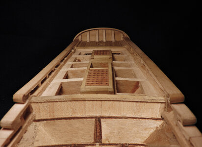
View attachment 382451
The "school of hard knocks" can be a tough one to graduate from, the lessons taught can be frustrating for sure.
The work and guidance, logic and reasons shown are helpful to some of less experienced ship modelers.
 
Hello Dave,

thank you very much for your great postings of your construction and modelling Sultana.

I will gladly follow your posts, because I have ordered the Sultana kit from Model Expo and two books about Sultana a few days ago.
Your idea of making your own plans and building with bulkheads and wood fillers is just what I would like to copy for my own build.

The original plans do not have enough lines to construct a satisfactory hull, as you have stated. And the basswood hull in the kit must not be very reliable, as I have read in other postings in this forum.
Sad to say I cannot handle computer programs to construct the bulkhead frames. I am a very poor PC- user.

Could I have copies of your computer drawings for the frames and the whole construction from you? Of course, I am willing to pay for all your work.

I am an old ship model builder. An article of my boxwood plank on frame model of French ketch La Salamandre was published in Model Shipwright magazine No. 80, the figurehead was on the back cover of No. 81.

Could I have copies of your computer drawings for the frames and the whole construction from you? Of course, I am willing to pay for all your work.

the problem with that is the model plans, images in the build log and anything to do with the Sultana are a commission and paid for by Model Expo to use in an up coming kit. They own all rights so i suggest you contact Model Expo and ask if you can have a copy of the working plans. If Marc agrees i can work with you and get you started on a plank on bulkhead model.
Are you saying that ME is considering this as a POB kit in 1/48?
 
Are you saying that ME is considering this as a POB kit in 1/48?

yes this is an up grade kit of their solid hull Sultana.

the plans are CAD drawn for the hull the original rigging plan will be from their solid hull kit, Instruction in the kit will be a revised version of this build log. The new Model Expo Sultana kit is 1:48 scale.
When will the kit be available depends on how fast i can finish the prototype.
 
dear Dave,
exchanging mails with your friend Marc brought no result with the plans and templates for Sultana.
He said he is reluctant to give away material of a planned kit. I can understand that from his point of view.

So I shall try to make something out of the hull block with original plans of Sultana from Maritime Museum at Greenwich which I ordered last week.

The rest of the kit is very poor. The plans and all materials are definitely unusable.

Best regards

Franz
 
Back
Top