I have to travel all of 10 miles to mine
-

Win a Free Custom Engraved Brass Coin!!!
As a way to introduce our brass coins to the community, we will raffle off a free coin during the month of August. Follow link ABOVE for instructions for entering.
-

PRE-ORDER SHIPS IN SCALE TODAY!
The beloved Ships in Scale Magazine is back and charting a new course for 2026!
Discover new skills, new techniques, and new inspirations in every issue.
NOTE THAT OUR FIRST ISSUE WILL BE JAN/FEB 2026
- Home
- Forums
- Ships of Scale Group Builds and Projects
- Group Build Archives
- Blandford Cross Section PoF Group Build
You are using an out of date browser. It may not display this or other websites correctly.
You should upgrade or use an alternative browser.
You should upgrade or use an alternative browser.
Donnie's HMS Blandford Cross Section Build: 1/32 Scale [COMPLETED BUILD]
Ok, so someone needs to come up with a list of when to use wooden treenails and then iron nails and where and when to use them. Not only that but what material to use - wood, brass, etc.
I see a broad range of uses here on the forum. If you really want to get into the details, brass is NOT going to be used on a ship anywhere. So, I do know (or think I know) that brass (if used) should be blackened to simulate nails, and also brass particles do not bleed into the wood. I made a bad mistake one time by using annealed steel nails and when I sanded the hull, steel powder got all into the wood grain - not happy about that at all. Never could get it out either.
I see a broad range of uses here on the forum. If you really want to get into the details, brass is NOT going to be used on a ship anywhere. So, I do know (or think I know) that brass (if used) should be blackened to simulate nails, and also brass particles do not bleed into the wood. I made a bad mistake one time by using annealed steel nails and when I sanded the hull, steel powder got all into the wood grain - not happy about that at all. Never could get it out either.
Brass wire looks very good as treenail in my opinion
Unlike Zoly, I am not a big fan of brass treenails. In the beginning, they shine bright, over time they oxidize and turn dark. Perhaps, on the small scale models, it might be the only choice. For the large scale I prefer using wood. 
I think you can do what pleases you! Historically, Hull planking used wooden tree nails, often with a wooden wedge driven into the nail to increase it grip. Deck planking used metal fasteners, with wooden “plugs” to fill the holes above the fasteners and keep the water out. Below deck, where water was not a constant issue, fasteners were metal...usually iron (except in the magazine).
To be accurate: no black tree nails on deck or Hull planking. But then again...it’s your ship and you can do what pleases you!
To be accurate: no black tree nails on deck or Hull planking. But then again...it’s your ship and you can do what pleases you!
Kurt Konrath
Kurt Konrath
Doc B, is that why you have tiny circles for fake treenails on hull?
I think you simulated with proper size SS needle turned on end to make it sharp.
I think you simulated with proper size SS needle turned on end to make it sharp.
As Dave explained in an earlier post, what we may see is the 'peg' sealed by caulking. Those pegs usually made from the same type of wood the deck laid.
Doc B, is that why you have tiny circles for fake treenails on hull?
I think you simulated with proper size SS needle turned on end to make it sharp.
Kurt: That effect is the result of a happy accident. I make those tree nails by drilling a hole, and gluing the end of a birch toothpick into the hole. I used CA glue and the result was the darker ring around the tree nails. I liked the effect, so I keep doing it!
Latest. I cut out the Main Deck Framing Plan for Main Beams. It seems that the MDB (Main Deck Beam) patterns are not quite correct. So, to stay on safe side, I just use the plan and cut out a template to use as a guide to set up my Bitts Pillars. I will Mill out the opening for the Sheaves. The Sheaves will be made out of steel or aluminum. Aluminum is easy to work with, but looks too fake in this application. Steel just has that heavy look to it. Hard to explain, but you can tell the difference.
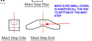
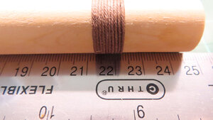
No problem. The total length of mast is 24.765 mm. You can just round that off to 25 mm. This length includes all of it like different width steps from the mast step. If you can give me a little while, I will use CAD and redraw in mm for you.
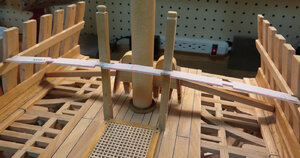
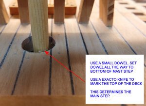
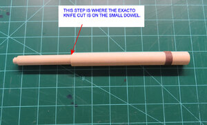
I am going to add more answer to this. Please report back. It is best not to just make all of mast as per plans as you really must use something like a small diameter dowel to lower down into hole until the dowel bottoms out or touched the very bottom of the Mast Step. Then you can take a marking tool or pencil and score the dowel with a line where the dowel meets flush w the top ovv fb the lower deck ( including the deck planking). This is the most accurate way. Then you will know what the limit is at the deck “step”. If I were to go exactly by the plans I would have in my case a 2 mm gap at deck. It is at this “step” is where the mast changes width again. The mast has three width changes and I am sure you are aware. The smallest diameter at lowest tip is for Mast Step in the block at floor. The next width change is from the top of Mast Step to the hole on the lower deck, the last mast diameter change will be the final and it is from the top of the lower deck that goes all the way to the upper end.
I hope this has not been too confusing of an explanation.
I hope this has not been too confusing of an explanation.
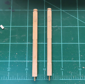
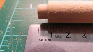
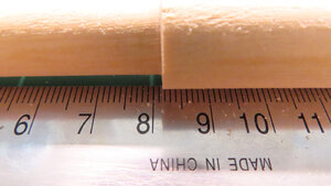
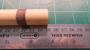
These are a series of pictures that show measurements in mm the best I could. I had a situation arise at the house that I had to attend. So maybe this will help explain why not to go exactly by plans.
There are NO two scratch build projects that are going to be exact. So, the images of the measurements are not going to be exactly like yours. Making this mark using a small dowel will make a huge difference in how your mast will set into the frame assembly as this mark is more of a REFERENCE point.
There are NO two scratch build projects that are going to be exact. So, the images of the measurements are not going to be exactly like yours. Making this mark using a small dowel will make a huge difference in how your mast will set into the frame assembly as this mark is more of a REFERENCE point.
Last edited:
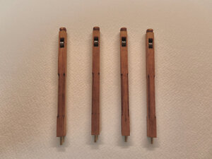
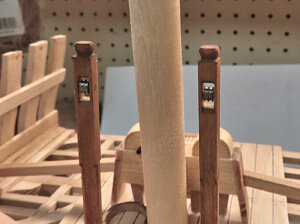
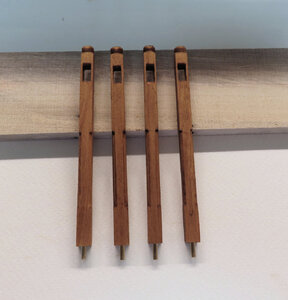
Almost finished with the Main Jeers Bitts. I will make pulleys and I also included a dxf drawing and a PDF for those that do not have CAD for the 1/32 scale. This might not apply to you, and I have not even made them yet, so we will see how my design for the pulleys work out.
I thought I would include the drawing for fun.
I thought I would include the drawing for fun.

Attachments
Kurt Konrath
Kurt Konrath
Thank you for all the extra work in showing the different mast diameters, and the reminder that models don't always match the plans.
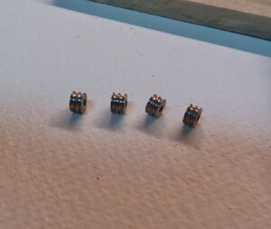
I cannot say that I am an expert at the lathe, but I can tell you that this is not for a beginner's first turn operation. Therefore, I present the pulleys. The openings of the bitts are a little too large, but it will have to do. When they are finished, then all votes can be cast. Sorry for no documentation on how I made these.
I will say this. I used a 6mm steel stock.
1) Turned down to 5mm.
2) Then drilled a 1.5mm hole into the stock about 40mm deep to have a one pass hole for all pulleys.
3) used a 60° tool bit to make grooves 1mm depth. +/1 about .1mm give or take (can't tell anyway)
4) used a straight cutoff tool to part each one. (each one at a time).
5) repeat the process over and over until you have made each one.
After a much-needed break, I will mount the pulleys. Time invested is about 4 hours straight. Having two sheaves in-one is probably not accurate and I get that. It is mostly for representation anyway. To make two sheaves for each bit would require even more time and effort than I would wish to apply here. And there could only be one sheave per bitt, so don't ask why I chose to do it this way.
The bitts are off on the plans, as you found out! nice job turning those sheaves!
Looks great!


