Both of you are correct, I will use one or combo of the suggestions. I was aware that the keel must have a positional reference. Both methods mentioned will provide this.
thank you
thank you

 |
As a way to introduce our brass coins to the community, we will raffle off a free coin during the month of August. Follow link ABOVE for instructions for entering. |
 |
 |
The beloved Ships in Scale Magazine is back and charting a new course for 2026! Discover new skills, new techniques, and new inspirations in every issue. NOTE THAT OUR FIRST ISSUE WILL BE JAN/FEB 2026 |
 |

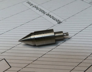
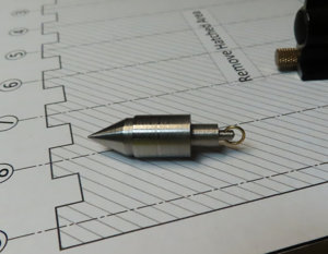
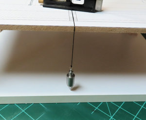
The tabletop must be dead level, though, Uwe!!Or with a perpendicular or lead, like I do it normally - If you have one, it is in my opinion that fastest and most accurate possibility
View attachment 127491



Hi Donald, Paul hereThis is now the official first opening remarks about my 1:32 build log of the Blandford. The first comment is that this is my first scratch build. I have been putting this off for a long time and now is the time. I also ordered the Blandford AOTS to help me with terminology.
First things first are getting the plans printed out. Since I have an HP 7740 Wide Format printer, this is at least one fortunate thing. Printing plans from pdf are not my forte'. However, a few adjustments needed to have the correct dimensions reflected correctly on the sheets.
I would like to expound on this if you do not mind. In the printer settings (advanced settings) there is a drop-down to choose between "Fit to Page" and "Actual Size". The default setting is "Fit to Page" and seems logical. I printed out a test page and from initial observation all is ok. But, closer inspection reveal that this is not the case. The first item to print was the Keel. One notch seems ok until I measured the full length and noticed a problem. Then I remembered the "Actual Size" selection from a long time ago dealing with the same situation. Printed the Keel again and it is now EXACT. I need to mention that the difference is NOT noticeable at first. the dimension difference is barely noticeable, but the dimensional error does add up. It is NOT the plans. It is the way the printer makes internal adjustments.
So, I include a small screenshot in case someone has this dilemma. Also, my basic printer dialog setting has "Tabloid" instead of the usual 11x17 settings. The tabloid is fine. Please take note that you might not have this problem. If you have a printing company doing this for you, mention "Actual Size". For those that already know this, then disregard as this is a new experience for me.
The next item that I felt was important was what method I was going to use to build the frames on. I must give credit to Norway (Knut) as I read his log on this. So, since my wife works at Hobby Lobby, I was able to get a 23 x 18 sheet of glass really cheap and it is 1/8 inches in thickness. I also grabbed a very thin transparency sheet. This one sheet is about $1.50 so, it is not major to buy more in case glues makes it messy.
I am not sure how this will work, but I think it will be ok. The glass serves as a strong flat surface. Then I lay my plan on the glass, then on top of the plans, I will lay my transparency sheet. The sheet is .030 inches, or 1/32", or .75mm in thickness. It seems so thin that I cannot tell the transparency sheet is there. Below are some samples of such:
View attachment 127217
Now this image below is just that the plans sheet static clinging to transparency. Kind of optical illusion.
It looks like the plans are on top, but the plan is underneath the transparency.
View attachment 127218
View attachment 127219
The wood selection: I have no experience here. I have always used "kit wood". I have contacted Dave at dlumberyard for some samples: Here is a list of samples. The (F) denotes all of the framing. The other woods are for (pillars, shot locker, pumps, etc.) is yet to be determined. My main concern, for now, is the framing selection. As you can tell, I am leaning towards a darker selection for framing. ONLY ONE (F) will be selected for framing. These are just choices. I am NOT mixing these.
So, there it is, as I am off to a start and waiting for some wood samples. I have always been a kit builder so I hope that I have not overloaded myself.
- Alder (F)
- Basswood
- Boxwood
- Cherry (F)
- Dogwood
- Holly
- Hornbeam
- Madrone (F)
- Swiss Pear
- Walnut (F)
Donald
Perfect work Donald for a beginner like me!......... I also ordered the Blandford AOTS to help me with terminology.
Donald

You can find a Book Review here in SOS:Perfect work Donald for a beginner like me!
What is the “Blandford AOTS to help me with terminology”?
Can you please tell me a bit more about it and where did you get it? I think it may help me with the terminology which I have a major problem understanding. I haven’t started building anything yet but I hope one day to do so.
Thank you.
