-

Win a Free Custom Engraved Brass Coin!!!
As a way to introduce our brass coins to the community, we will raffle off a free coin during the month of August. Follow link ABOVE for instructions for entering.
-

PRE-ORDER SHIPS IN SCALE TODAY!
The beloved Ships in Scale Magazine is back and charting a new course for 2026!
Discover new skills, new techniques, and new inspirations in every issue.
NOTE THAT OUR FIRST ISSUE WILL BE JAN/FEB 2026
You are using an out of date browser. It may not display this or other websites correctly.
You should upgrade or use an alternative browser.
You should upgrade or use an alternative browser.
Don's Santisima Trinidad by OcCre
- Thread starter donlong
- Start date
- Watchers 16
-
- Tags
- occre santisima trinidad
Thanks Clair.
I checked out your log on the Victory. You were smart to make the changes up front. It looks really good.
I am using the Victory to some degree to get an idea of what the ST might have looked like. After all, the guys that designed the ST were from Ireland. From what I have found, Spain did out source some of their ship design work. I think most designers were more interested in speed, maneuverability and reliability than interior design. So I think cabins and galleries were pretty much the same from ship to ship regardless of country.
I know modifying a kit model is not as easy as it may sound; at least it hasn’t been for me. Instead of cutting everything at one time, I am cutting as I go. I am sure if I had decided to add the cabins at the beginning of the build, things would have gone a lot smoother for me.
So far; so good.
Later,
Don
Thanks Popeye.
I have to admit it has been time consuming doing it this way. Even with the paper patterns, there is still a lot of sanding, filing, fitting and refitting until it is just right. I found after I have the decks in place, there will be even more sanding and filing to make sure the relationship between each deck is correct. But you know, in the end, it is all worth it. It will be a thing of beauty and I did it with my own two little hands.
Thanks again,
Don
Section 3 – Stern Decking
Hi there,
Remembering back, I made a paper pattern to get the general size and fit for the 1st battery deck. Once the deck was cut out, it was then cut in two pieces, sanded until it fit, planked and then installed. Then I used the gallery form for that deck as a pattern. Processed it, then I used that piece as a pattern for the other side. Once done, they were fitted and installed. Then I planked the two decks.
The exact same process was used for the 2nd battery deck. One thing you might consider is using some support pieces to hold the deck in its proper place when gluing the deck.
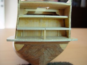
Here is a picture of the supports I used. Once the deck has been mounted, you can remove them. Use just enough glue to hold the support but not permanently glue it in place.

Here is the 2nd battery deck installed.

These decks are roughed in, meaning they have not been adjusted for alignment from top to bottom or side to side. I have that process figured out but am not ready to do it just yet.
Just for grins, I wanted to see if the placement of the decks were where they should be. I placed a cannon on each of the gallery decks and pointed the barrel to the cannon port in the hull that was next to it. If the gallery deck was mounted correctly, the center line of the barrel should be close to the center line of the port.
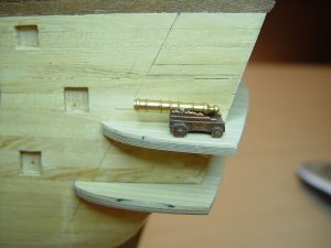
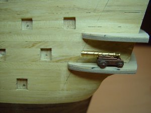
As you can see, they are very close.
All I can say is I’m happy!!!
The 3rd battery deck is just an extension of the existing deck and the addition of the gallery decks. The quarter deck requires only an extension. I will be doing that next. Once this is done, I will fashion the top and bottom pieces of the galleries. They are currently in lead and not in too good a shape so new wooden ones are in order.
When I have the top and bottom gallery pieces made and installed, I will post again. Pictures of the process will be supplied also.
Later,
Don
Hi there,
Remembering back, I made a paper pattern to get the general size and fit for the 1st battery deck. Once the deck was cut out, it was then cut in two pieces, sanded until it fit, planked and then installed. Then I used the gallery form for that deck as a pattern. Processed it, then I used that piece as a pattern for the other side. Once done, they were fitted and installed. Then I planked the two decks.
The exact same process was used for the 2nd battery deck. One thing you might consider is using some support pieces to hold the deck in its proper place when gluing the deck.

Here is a picture of the supports I used. Once the deck has been mounted, you can remove them. Use just enough glue to hold the support but not permanently glue it in place.

Here is the 2nd battery deck installed.

These decks are roughed in, meaning they have not been adjusted for alignment from top to bottom or side to side. I have that process figured out but am not ready to do it just yet.
Just for grins, I wanted to see if the placement of the decks were where they should be. I placed a cannon on each of the gallery decks and pointed the barrel to the cannon port in the hull that was next to it. If the gallery deck was mounted correctly, the center line of the barrel should be close to the center line of the port.


As you can see, they are very close.
All I can say is I’m happy!!!
The 3rd battery deck is just an extension of the existing deck and the addition of the gallery decks. The quarter deck requires only an extension. I will be doing that next. Once this is done, I will fashion the top and bottom pieces of the galleries. They are currently in lead and not in too good a shape so new wooden ones are in order.
When I have the top and bottom gallery pieces made and installed, I will post again. Pictures of the process will be supplied also.
Later,
Don
Last edited:
Hi Don, great work you are doing here. About the tiles I was just wandering if you found any information that I didn't, and as popeye said it looks great planked or tiled...
As you can imagine I'm following you posts with great interest. I plan to do a lot of changes to the stern of my ST as well. I have some question about what you already done. Are you going to do the balconies all around the stern? are they going all the way to the galleries? if not, if the galleries are going to be covered, did you account for the thickness of the "cover"? do you see what I mean? By looking at you last pictures if we add the thickness of the galleries cover to the position were the deck ends is it not to close to the gun port?
As you can imagine I'm following you posts with great interest. I plan to do a lot of changes to the stern of my ST as well. I have some question about what you already done. Are you going to do the balconies all around the stern? are they going all the way to the galleries? if not, if the galleries are going to be covered, did you account for the thickness of the "cover"? do you see what I mean? By looking at you last pictures if we add the thickness of the galleries cover to the position were the deck ends is it not to close to the gun port?
Hey Anguirel,
Thanks for your comments. As you are probably aware, there are no definitive plans of the stern or the galleries. There are only a few eye witness accounts of what the ST even looked like the day of the Trafalgar battle. So you have to guess at the tile.
When she was first launched, I would think she had tile and most likely some checker board pattern. That was very popular back then. After finding out she did not handle well, it is difficult to say how much Spain was willing to put in her for creature comforts. By 1797, Admiral Jose de Mazarredo, the Captain-General at Cadiz proposed beaching her at Cadiz and using her as a defensive gun platform. He was over ruled and they spent until 1804 refitting the ship by adding the additional deck and guns. Of course this compromised her sea worthiness even more.
I believe what you do in the cabins, depends on the size of the windows. If they are larger than the kit, then I would tile the floors and add some furniture. It is not that you or anyone would be looking in there for it, but you would be able to tell there were things in there in general terms. Remember it is the illusion that you want to create. Make people think there are cabins with tables, chairs, etc. Hope this makes sense.
Once again, based on research, the balconies were only on the stern on the 2nd and 3rd battery decks. The galleries did not have balconies. Perhaps I should say open balconies. From some of the drawings I have seen, you could walk out onto a platform and look out the gallery windows. I don’t believe you could walk around from the stern to the galleries. The drawings show a door from the cabin to the gallery platform. What looks like the middle window for the 2nd and 3rd stern windows in the kit is actually a door to goes out onto the stern balcony. Crespo shows it as a double door. You can see that on pages 9 and 10 in the Doors and Windows section of my log.
Doing the decks the way I did, it allows me to install the ‘cover’ either on the deck or on the edge of the deck. I am leaning towards on the deck. I will not be using any of the kit pieces to cover the galleries. I plan on making these parts. Therefore thickness is not an issue for me.
When I installed the gallery decks I had already compensated for the one plank they use in the kit that runs on the bow side of the gallery decks. I thought by doing it this way, I would get a cleaner look. So the distance to the gun port is not an issue. My decks will not extend any further towards the bow. Even if I changed my mind and decided the install the ‘cover’ to the edge of the deck, it is only a simple matter to file, sand or cut the bow end of these decks back a little.
Hope this answers your questions. If not, let me know and I will add some pictures.
Later,
Don
Popeye,
OOPS I guess a picture is not worth a thousand words. Cannon are not mounted on the gallery decks although it would have been a great tactical surprise to the enemy. I was only showing the fact that my decks were mounted in the correct locations as opposed to how they were in the kit.
The only thing I had other than a ruler was a cannon. With the curvature of the decks at the stern, I thought it would be a better visual effect to show the true placement of the decks. Sorry my post was confusing.
Later,
Don
Section 3 – Stern Decking
Hello to all,
Well it is 104°F outside (I live in Mesa, Arizona) and I am here in the garage hammering away on the ST. When last we met, I had the 3rd battery deck extension to make and install. You know me and patterns;
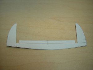
Here is the pattern I made for the 3rd battery deck. Since it is only an extension, I incorporated the quarter gallery decks also.
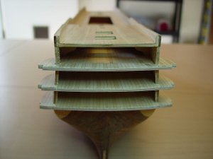
Here is the deck installed. When planking, I did not bother to match the color variation between the planks. You will never see the original deck and the extension together again except for this moment in time. When the cabin is installed the separation will be hidden.
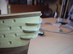
Here is another shot from a different angle. The stern decks have been sanded to the correct balcony lengths and angle to the stern. To make sure this is correct, you can use a plank as I have shown in the following photo and side it horizontally around the three decks to see if they are the same and at the correct angle.
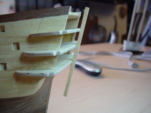
Here is a shot of that. If there is a gap between any of the decks and the plank, then you know you have to sand at least one of the other decks until the gap goes away.
I keep using the word angle. This operation is all about angles. There is the angle of the deck extensions vs. the angle of the stern itself from top to bottom. There will be the top to bottom angles of the gallery decks. There is the angle of the deck extensions to each other and to the deck it is representing. So for this to work, you must pay attention to these angles.
The next thing I wanted to establish is the stern plate and how it will fit. In my case, I will only be using the decorative band around the stern and not the entire stern plate. For the purpose of fitting the decorative panel, however, I am using the entire stern plate. It is more stable at this point in the process.
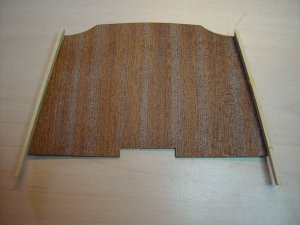
You need to select the shape of the stern. There are several out there. I decided to use the one that came with the kit. There is a piece of wood that holds the three stern lights that is mounted to the stern plate. For establishing the proper stern mount, I glued only the side bands to the stern plate. These pieces will butt up to the outer shell of the quarter gallery cover.
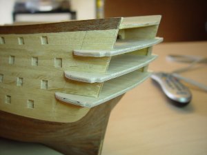
If you notice, there are notches in the gallery decks. When I installed the decks, I made them a bit larger than I needed. I always do that just in case I run into a problem. The notches are where the stern decorative plate and band will mount to the deck
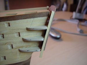
As you can see the stern plate fits nicely. All I need to do is trim and shape the excess on the gallery decks and this part of the operation will be done.
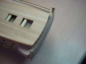
I waited before extending the quarter deck. Once I permanently mount the stern decorative trim, I can finish the deck extension.
My next task is the dreaded stern windows. I think this will end up being a scratch build also. So far nothing I have done has looked right or fit right. Without the balconies (like the Victory), it works fine. With the balconies it all works great except for the outer most windows on the 2nd and 3rd battery decks. So the next time I post, I will have a window solution.
Later,
Don
Hello to all,
Well it is 104°F outside (I live in Mesa, Arizona) and I am here in the garage hammering away on the ST. When last we met, I had the 3rd battery deck extension to make and install. You know me and patterns;

Here is the pattern I made for the 3rd battery deck. Since it is only an extension, I incorporated the quarter gallery decks also.

Here is the deck installed. When planking, I did not bother to match the color variation between the planks. You will never see the original deck and the extension together again except for this moment in time. When the cabin is installed the separation will be hidden.

Here is another shot from a different angle. The stern decks have been sanded to the correct balcony lengths and angle to the stern. To make sure this is correct, you can use a plank as I have shown in the following photo and side it horizontally around the three decks to see if they are the same and at the correct angle.

Here is a shot of that. If there is a gap between any of the decks and the plank, then you know you have to sand at least one of the other decks until the gap goes away.
I keep using the word angle. This operation is all about angles. There is the angle of the deck extensions vs. the angle of the stern itself from top to bottom. There will be the top to bottom angles of the gallery decks. There is the angle of the deck extensions to each other and to the deck it is representing. So for this to work, you must pay attention to these angles.
The next thing I wanted to establish is the stern plate and how it will fit. In my case, I will only be using the decorative band around the stern and not the entire stern plate. For the purpose of fitting the decorative panel, however, I am using the entire stern plate. It is more stable at this point in the process.

You need to select the shape of the stern. There are several out there. I decided to use the one that came with the kit. There is a piece of wood that holds the three stern lights that is mounted to the stern plate. For establishing the proper stern mount, I glued only the side bands to the stern plate. These pieces will butt up to the outer shell of the quarter gallery cover.

If you notice, there are notches in the gallery decks. When I installed the decks, I made them a bit larger than I needed. I always do that just in case I run into a problem. The notches are where the stern decorative plate and band will mount to the deck

As you can see the stern plate fits nicely. All I need to do is trim and shape the excess on the gallery decks and this part of the operation will be done.

I waited before extending the quarter deck. Once I permanently mount the stern decorative trim, I can finish the deck extension.
My next task is the dreaded stern windows. I think this will end up being a scratch build also. So far nothing I have done has looked right or fit right. Without the balconies (like the Victory), it works fine. With the balconies it all works great except for the outer most windows on the 2nd and 3rd battery decks. So the next time I post, I will have a window solution.
Later,
Don
Last edited:
Very impressive work
JCT, Popeye & Edwin,
Gentlemen thanks for your comments. After a lot of studying on the stern, I have finally figured it out. I solved my window problem too. I am in the process of finishing the rough cut for a new stern plate. I will take some pictures and explain what I have done in the next few days.
So stay tuned and thanks again.
Later,
Don
Section 3 – Stern Decking
Hi guys,
The largest problem I have had to face is the stern plate. If you think about it, the plate must bow outwards from the stern AND bow horizontally or from side-to-side. All pictures in this section are rough cuts. Trying to make it perfect the first time only makes your stomach hurt.
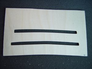
The first thing is to make a new stern plate. The slots that you see here are for the 2nd and 3rd battery decks. Notice the curvature at the bottom of the plate. When mounted on the stern of the ship, the curvature will actually sit flat as it bows outwards from the ship. In my case, I worked from the bottom of the plate, up. Once you have the bottom of the plate with the correct curvature, all measurements will be made from this curve. So you know, I used the first battery deck brass window frame that came with the kit to get the correct curvature. Also, make the plate larger than you need it. This will be necessary for several reasons I will point out as we go through this section.
Once you have the curvature set, take the top and bottom measurements for the 2nd battery deck on the ship and plot them on your back plane. I made measurements every quarter inch until I could see where the deck would be. How you cut these slots is up to you. I used an x-acto knife and a file. I checked it many times as I cut the slot.
Do the same process for the 3rd battery deck.
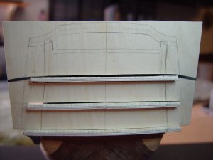
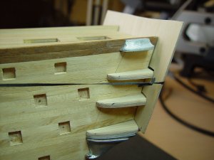
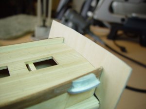
When done, the plate should fit onto the stern of the ship. You may want to draw reference points on the stern plate to use for other purposes. The black you see on the plate is where I tied it to the ship so it would be a little easier to work with when locating the placement of the windows and doors. At this point you might be thinking he cut it too far. It will show in the decorative band on the plate. Not so.

Remember I was having the problem with the outer windows and the sides of the ship? What I did was take the Crespo drawing and stretch it horizontally until the column between the outer window and the next window in, fit directly over the edge of the ship.
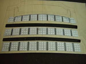
This places the outer window looking into the gallery instead of looking at the edge of the ship. Since the stern plate is actually a little wider than needed, I can move the decorative band out just a little to compensate for the placement of the outer window.
The next step will be open the windows and doors on the plate to make sure they are in the correct place. Since I have taken the time to draw this out on the plate, I should have no problems. Once I am happy with the plate. The next step will be the cabins. The cabins will need to be completely done before I can install the plate and galleries. The individual window panes will be made from square copper wire. Something in the range of 22 to 25 gauge should do nicely.
If you have any questions, fire away.
Later,
Don
Hi guys,
The largest problem I have had to face is the stern plate. If you think about it, the plate must bow outwards from the stern AND bow horizontally or from side-to-side. All pictures in this section are rough cuts. Trying to make it perfect the first time only makes your stomach hurt.

The first thing is to make a new stern plate. The slots that you see here are for the 2nd and 3rd battery decks. Notice the curvature at the bottom of the plate. When mounted on the stern of the ship, the curvature will actually sit flat as it bows outwards from the ship. In my case, I worked from the bottom of the plate, up. Once you have the bottom of the plate with the correct curvature, all measurements will be made from this curve. So you know, I used the first battery deck brass window frame that came with the kit to get the correct curvature. Also, make the plate larger than you need it. This will be necessary for several reasons I will point out as we go through this section.
Once you have the curvature set, take the top and bottom measurements for the 2nd battery deck on the ship and plot them on your back plane. I made measurements every quarter inch until I could see where the deck would be. How you cut these slots is up to you. I used an x-acto knife and a file. I checked it many times as I cut the slot.
Do the same process for the 3rd battery deck.


When done, the plate should fit onto the stern of the ship. You may want to draw reference points on the stern plate to use for other purposes. The black you see on the plate is where I tied it to the ship so it would be a little easier to work with when locating the placement of the windows and doors. At this point you might be thinking he cut it too far. It will show in the decorative band on the plate. Not so.

Remember I was having the problem with the outer windows and the sides of the ship? What I did was take the Crespo drawing and stretch it horizontally until the column between the outer window and the next window in, fit directly over the edge of the ship.

This places the outer window looking into the gallery instead of looking at the edge of the ship. Since the stern plate is actually a little wider than needed, I can move the decorative band out just a little to compensate for the placement of the outer window.
The next step will be open the windows and doors on the plate to make sure they are in the correct place. Since I have taken the time to draw this out on the plate, I should have no problems. Once I am happy with the plate. The next step will be the cabins. The cabins will need to be completely done before I can install the plate and galleries. The individual window panes will be made from square copper wire. Something in the range of 22 to 25 gauge should do nicely.
If you have any questions, fire away.
Later,
Don
Last edited:
Section 3 – Stern Decking
It’s me again.
I forgot to mention that the stern plate will now fit the ship as originally intended in the kit. The extension will not be necessary. The decks will protrude through the new stern plate thus creating the balconies. The first battery deck will protrude beyond the plate also but will be cut flush with the stern plate once it is glued in place. Doing the plate this way, it will allow the external band around the stern plate to fit without having the modify the quarterdeck railings.
Later,
Don
Section 3 – Stern Build
Hello to all,
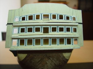
Well here it is. The holy grail to stern plates. At least for the ST and not just because I made it. As you can see, now the outer most windows look into the galleries. There are door cut outs for the 2nd and 3rd battery decks. The windows are large and should afford a good view into the cabins as well as looking out if you were tiny enough to fit in the cabins. Just kidding.
Once again it is tied to the stern so I could take the photos. I also trimmed it to the shape required. This is the shape provided by the kit. Here are some side shots to show the windows from the gallery point of view.
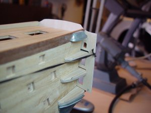
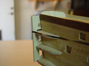
Before the plate can be glued in place, I need to complete the gallery shells, the cabins and make the window panes. I need to remove the paper template and clean up the window cut outs just a little. My gut tells me I should probably do the decorations on the stern plate or have them ready before I glue it in place.
Other than the fact this is a slow process to figure this entire thing out, I am pleased with it.
Later,
Don
Hello to all,

Well here it is. The holy grail to stern plates. At least for the ST and not just because I made it. As you can see, now the outer most windows look into the galleries. There are door cut outs for the 2nd and 3rd battery decks. The windows are large and should afford a good view into the cabins as well as looking out if you were tiny enough to fit in the cabins. Just kidding.
Once again it is tied to the stern so I could take the photos. I also trimmed it to the shape required. This is the shape provided by the kit. Here are some side shots to show the windows from the gallery point of view.


Before the plate can be glued in place, I need to complete the gallery shells, the cabins and make the window panes. I need to remove the paper template and clean up the window cut outs just a little. My gut tells me I should probably do the decorations on the stern plate or have them ready before I glue it in place.
Other than the fact this is a slow process to figure this entire thing out, I am pleased with it.
Later,
Don
Last edited:
Thanks Popeye.
I am ready to add my next installment for the galleries. It should be up shortly. For some reason, this seems to get easier as I move forward.
Later,
Don
I am ready to add my next installment for the galleries. It should be up shortly. For some reason, this seems to get easier as I move forward.
Later,
Don
Section 3 – Gallery
I’m back,
The stern is becoming a puzzle with many pieces. The advantage is I already know where each piece goes. I have the stern plate under control. After some thought, I decided to figure out what to do the galleries. The first thing I did was to build a shell that will form the shape of the gallery. I have a bunch of floor planking pieces so I built the shell from that.
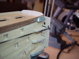
The shape of the gallery should conform to the top and bottom lead decorator parts. I glued those in place using Titebond so I can remove them later to see if I can clean them up for use on the ST. I also have dry fitted the stern plate in place so I can see how it and the gallery form my fit together.
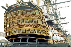
Looking at the stern of the Victory, this looks like a good solution for mating the galleries to the stern plate.
To make the form without gluing it to the ST, I glued each plank (one at a time) to each other. I started at the forward end of the gallery and made sure the plank would fit between the two lead pieces. The Titebond dries pretty quickly. Quick enough that you can add the additional planks without waiting more than a minute between planks. As I set each plank, I made sure it fit between the top and bottom lead pieces.
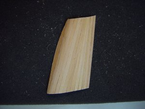
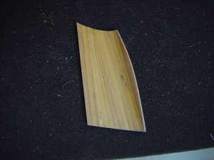
When satisfied with the fit, I would coat the inside of the form with a watered down glue solution.
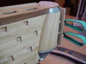
When I finished the basic form, I then added some planks to the forward end and sanded them until they fit tight to the hull.
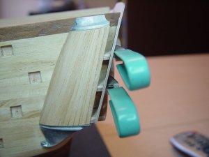
Here is the dry fit of the gallery form. As you can see the transition from the gallery to the stern plate should be very easy to create.
The gallery form is fairly delicate. If I fine it is too delicate, I can add another layer of planking to stiffen it up. I honestly don't believe that will be necessary.
Well gotta go. I have the other gallery form to make. Then I will determine what is next. I am guessing the windows for the galleries should be next, then the doors that allow access to the galleries from the cabins.
Later,
Don
I’m back,
The stern is becoming a puzzle with many pieces. The advantage is I already know where each piece goes. I have the stern plate under control. After some thought, I decided to figure out what to do the galleries. The first thing I did was to build a shell that will form the shape of the gallery. I have a bunch of floor planking pieces so I built the shell from that.

The shape of the gallery should conform to the top and bottom lead decorator parts. I glued those in place using Titebond so I can remove them later to see if I can clean them up for use on the ST. I also have dry fitted the stern plate in place so I can see how it and the gallery form my fit together.

Looking at the stern of the Victory, this looks like a good solution for mating the galleries to the stern plate.
To make the form without gluing it to the ST, I glued each plank (one at a time) to each other. I started at the forward end of the gallery and made sure the plank would fit between the two lead pieces. The Titebond dries pretty quickly. Quick enough that you can add the additional planks without waiting more than a minute between planks. As I set each plank, I made sure it fit between the top and bottom lead pieces.


When satisfied with the fit, I would coat the inside of the form with a watered down glue solution.

When I finished the basic form, I then added some planks to the forward end and sanded them until they fit tight to the hull.

Here is the dry fit of the gallery form. As you can see the transition from the gallery to the stern plate should be very easy to create.
The gallery form is fairly delicate. If I fine it is too delicate, I can add another layer of planking to stiffen it up. I honestly don't believe that will be necessary.
Well gotta go. I have the other gallery form to make. Then I will determine what is next. I am guessing the windows for the galleries should be next, then the doors that allow access to the galleries from the cabins.
Later,
Don
Last edited:
Popeye,
You are correct on the thinkness of the gallery walls. The windows would not look right being thick. What I did was laminate an index card to the inside of the gallery shell. It makes it just rigid enough to take the cutting of the windows plus it makes the interior wall of the gallery white.
There is no bending of the wood the way I did it. I used 1x3 ramin strips glued edge to edge. The curves form naturally that way. I will take some pictures of it before I mount them.
So far it is going very well. It is just very time consuming cutting the windows and making sure all the pieces fit together properly.
Later,
Don
Thanks Popeye.
The roof part of the gallery was the easy part for me so I did not pay much attention to it. I am thinking the space is so small that I can insert a piece of wood about 3/16 thick and blend it to the top lead piece. I have a feeling it will look like it belongs there. Worse case, I can aways fashion a new top piece.
The planking was installed in the direction described in the kit instructions. For some reason, it never occurred to me to make them run parallel with the hull. As you say it will be painted anyway so it will never get noticed.
Thanks for keeping me true to this modification. Your inputs are always taken with a lot of consideration.
Later,
Don
Section 3 – Gallery
Here is a progress report.
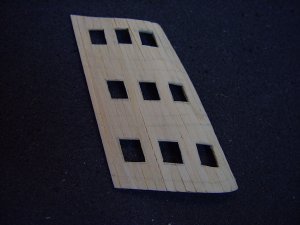
I have rough cut the windows on the gallery shell.
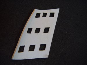
To give it a little more strength, I laminated an index card to the inside of the shell. It gives the interior wall a white, painted or finished look. It also hides the wood seams. To make the shell, I used 1x3 ramin strips. The only issue I have is the ramin (in this case) wants to bow and flex a bit. Since it will be glued to each deck, the hull and the stern plate, there will be no problem in maintaining the proper shape.
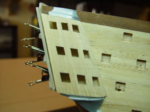
This is a dry fit shot of the shell to the ship. While it does not show it in this shot, the stern plate butts up to the shell perfectly.
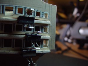
Here is a shot looking into the gallery from the stern plate. As you can see, by moving the outer most stern windows, you can now see into the gallery.
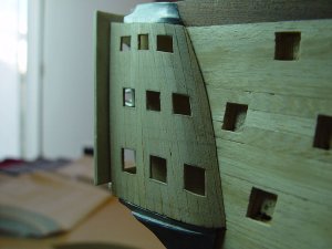
Here is the same shot but from the opposite direction. The outside of the shell looks rough but it is almost completely covered with decorative items. The shell will get a light, watered down coat of wood filler, followed by a light sanding and then sealed. This will allow for a better paintable surface and finished look.
Well the time has come for me to work on the cabins. When completed I will do the window panes for the stern plate and gallery forms. When that is done, the stern plate and gallery forms will be permanently installed. Then I will finish up with all of the outside decorations.
Once again I am happy with the results and it is becoming easier to do as I move forward. You need to be prepared to bury yourself in a project like this for many hours. With a ship this size or the size it represents, there is a lot of repetition. Windows, cannon ports… even the planking. Many hours... repetition, repetition, repetition... many hours.
Later,
Don
Here is a progress report.

I have rough cut the windows on the gallery shell.

To give it a little more strength, I laminated an index card to the inside of the shell. It gives the interior wall a white, painted or finished look. It also hides the wood seams. To make the shell, I used 1x3 ramin strips. The only issue I have is the ramin (in this case) wants to bow and flex a bit. Since it will be glued to each deck, the hull and the stern plate, there will be no problem in maintaining the proper shape.

This is a dry fit shot of the shell to the ship. While it does not show it in this shot, the stern plate butts up to the shell perfectly.

Here is a shot looking into the gallery from the stern plate. As you can see, by moving the outer most stern windows, you can now see into the gallery.

Here is the same shot but from the opposite direction. The outside of the shell looks rough but it is almost completely covered with decorative items. The shell will get a light, watered down coat of wood filler, followed by a light sanding and then sealed. This will allow for a better paintable surface and finished look.
Well the time has come for me to work on the cabins. When completed I will do the window panes for the stern plate and gallery forms. When that is done, the stern plate and gallery forms will be permanently installed. Then I will finish up with all of the outside decorations.
Once again I am happy with the results and it is becoming easier to do as I move forward. You need to be prepared to bury yourself in a project like this for many hours. With a ship this size or the size it represents, there is a lot of repetition. Windows, cannon ports… even the planking. Many hours... repetition, repetition, repetition... many hours.
Later,
Don
Last edited:
Thanks Popeye!!!
You are correct about making the windows square although square is probably the wrong term. Mine need to be straight. Most of the windows on the ST have a slant to them. If you don't sand them lengthwise, it will leave gouges everywhere. So far no splitting. I really took my time on it and made sure the area I was sanding was supported well.
Well thanks again for your inputs and comments. Onward to the cabins. Maybe they will end up in the Ancient Seafarers Periodical or Better Homes and Gardens.
Later,
Don


