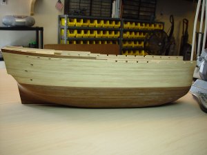
Don's Santisima Trinidad by OcCre

Hi,
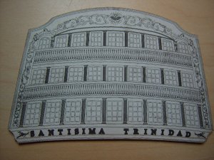
I’m back again. As promised, this is the first installment of my scratch build stern section of the Santisima Trinidad. If you remember back on page 7; about 6 posts down, I had some concerns on the stern. Donnie had to cut away part of his deck railing in order to get the stern to mount properly. After checking the parts to the drawing, I found the parts were off by about 2mm.
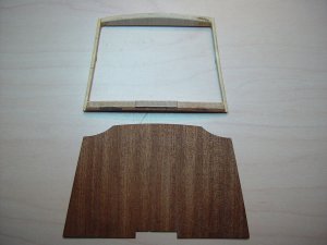
DSC00112-1.JPG
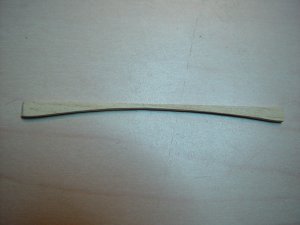
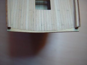
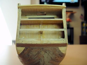
To solve the problem, I made an extension that would push the stern plate out to the proper placement and therefore no deck railing modification would be required.
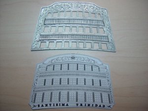
DSC00113-1.JPG
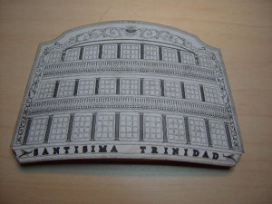
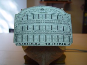
Since no one really knows what the ST stern looked like when she sank, I have decided to use Joaquin Rodriguez Crespo’s rendition of what he thought it looked like in 1778. This closely follows the metal plate that came with the kit.

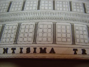
Looking at the stern, there is a lot of work required to replicate the metal plate to give it better definition. My approach will be to break it down into manageable sections. There is the initial layout, window frames, the window panels, doors, the columns between the windows, the platforms (balconies), railings, balusters, lettering (Santisima Trinidad), borders and the decorations.
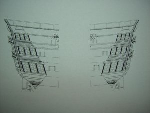
DSC00118-1.JPG
These same sections will hold true for the quarter galleries as well. There may be other sections but these are the ones that stand out the most.

SECTION 1 - Layout
One of the biggest problems I have had with the layout, is the placement of the windows. The metal plate from the kit is pretty beat up. So laying it on the stern back plate and tracing the windows is a hugh waste of time. It would be very labor intensive to correct all the errors.
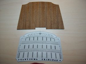
DSC00116-1.JPG
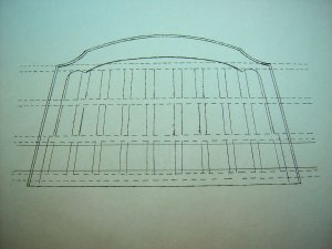
I took the drawing and reduced it to the 1:90 scale and printed it out. Then I cut it out to use as a template. The cutout will be glued to the back plate using Titebond. One point I need to make, I will have to make a new back plate. As you can see the rendition has a slightly different shape to it... just enough to warrant a new back plate. Once the windows are cut out, I can soak it in water to remove the balance of the template. As you can see, this will leave a very clean window arrangement.

This is all I have for now. I will come back with the results of the window cutting.

Later,

Don
 
Last edited:
Hi,

SECTION 1 – Layout (continued)

Ok, from the last post, I determined that I needed to make a new stern back plate.

DSC00120-1.JPG
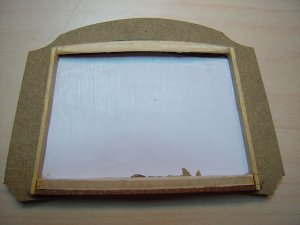
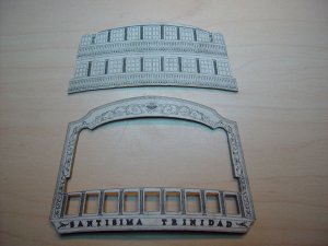
Here is the new back plate. I took some pressboard, about 2.7mm thick and glued the ST template to it using a watered down Titebond solution. I wanted the new stern plate to be thicker than the original one to give some definition to the windows once they were cut out. Once the glue dried, I cut out the new stern plate.

DSC00123-1.JPG
Next, I glued the stern extension to the new stern plate.

DSC00126-1.JPG
I did not realize it at the time but the curvature at the bottom of the stern is more pronounced than it is at the top.

DSC00128-1.JPG
Since the new plate had to be pushed out 2mm to correct its mounting position, I also had to create a small deck bridge to fill in the gap between the quarterdeck and the back of the stern plate.

DSC00131-1.JPG
Here is the bridge installed on the quarterdeck.

DSC00129-1.JPG
This is a shot of the dry fit to the stern of the ST. This will actually be a little higher on the stern but it gives you an idea of things to come.

This completes SECTION 1 – Layout.

SECTION 2 – Windows & Doors

Next is to cut out the doors and windows. The ST had a door to each balcony. You can see them on the stern shot above.

DSC00130-1.JPG
In this case, I will remove the pressboard leaving no sign of the window or door. The window & door frames will be mounted inside the cutout.

This is all I have for the moment.

Later,

Don
 
Last edited:
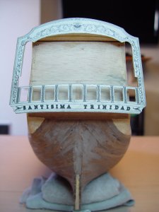
Thanks Popeye.

Working with the pressboard really has its advantages. The window cut outs are coming out very clean. The other thing is the pressboard holds its shape. I found you cannot get it too wet or it will delaminate. So a little moisture goes a long way. Once it is dry, it is done. I am cutting out the lower windows in between other home projects so it is a little slow. When that is done, I will probably cut out the sections for the two balconies to add to the depth. I can pick up 5mm doing that way. The balconies do not protrude too far off the stern. I am guessing they were probably no more that 6 feet deep in real life.

I will take some more pictures when I get the windows cut out and the balconies removed.

Thanks again.

Later,

Don
 
Good work Don, I will be following your posts with great interest. I will avoid lots of headaches because of you...
 
Very impressive Don. It really shows and pays off when you are able to go beyond the kits suggestions / instructions.

I am redoing all of my Yard Lifts. I see that I made a big mistake. OcCre's Plates can be really confusing and some mistakes in their documentation in the hands of inexperienced like me spells disaster.

However, I would say that 95% of what they have on the plates are good, but the belaying pin outs are almost unusable.

I made some notes in my recent build log about the lifts.
 
Anguirel,

Thanks for the vote of confidence. While I broke the scratch build of the stern into different sections, it still sometimes turns out to be a ‘plan as you go’ project. Example: I am cutting out the lower windows in the stern. Just for grins, I put the stern section on the ship to see how it looks and what do I see, the back edge of the ship showing in half of the far windows. This also means I will see the quarter galleries in these windows when I begin to build them. So now I am thinking, I should wrap the balconies around the stern so it is connected. I have seen some that have done that, but did not know why. Now I think I understand it. If I don’t wrap balconies, it will look dumb.

I have two more of the lower windows to cut out. When I am done, I will put up a few pictures to show you what I am talking about.

Thanks again for your comments. It is always good to know someone can benefit from this log.

Later,

Don
 
Thanks Donnie.

I think I have proven if you are going to build these ships correctly, you have to go beyond the scope of the instructions; at least with the OcCre plates. Actually, I have been following your build log more so than the instructions. And as Anguirel said, I have avoided a lot of headaches because of you.

I saw in one log, (at another site) the count of the belaying pins was wrong. The kit had too few. I don’t know if this is true or not as belaying pins are the least of my concerns at the moment. Even so, I still follow your log so I at least know what the ‘Coming Attractions’ are going to be. If I see something that is a problem for you, it gives me a little time to think about it.

I will check out your notes and put it in the “Things to be concerned about” column.

Later,

Don
 
Popeye,

Thanks for the input. I checked out your build log on the Gothenborg. First, let me say WOW!! That is really a nice ship. Second, I see what you mean about the stern treatment. This is one of those times when my lack of experience building these ships is showing. It would have been much easier to put in the detail work before then after. BUT with that said, I am in a good place to correct it now since the stern plate I am working on has not been permanently installed.

Cutting out the windows gives me time to think about it plus now that I recognize there is an issue, I need to see how the galleries fit to stern plate.

Thanks again,

Don
 
Hi,
SECTION 2 – Windows & Doors (continued)

Thought I would give an update on my progress on the scratch stern build. I have cut out the bottom section windows on the rear stern plate. I also removed the entire section for the other two rows of window on the plate so I can add the balconies.

DSC00132-1.JPG
Here is what that looks like.

DSC00133-1.JPG
Here is what it looks like on the stern of the ST.

You know, I have done some carpentry work in my time but I am a bit confused on the curvature of the windows of the stern.

DSC00136-1.JPG
The Crespo drawing (the one I used for my template) seems to have more of an arch in their placement than the windows in the OcCre kit. This makes putting in the floor to the balcony or galleries very hard to do without imposing on the windows below. I am wondering if Crespo used some sort of perspective in his artwork to depict the curvature of the stern itself. After reviewing a lot of pictures and data on the stern, I have determined that I will have to make a new template and stern plate, using the placement of the windows according to the OcCre kit and the size according to Crespo.

As you know I also ran into an issue with the far side stern windows showing the stern if you look though the windows into the ship. Popeye suggested that I modify the stern to actually show the galleries. This seems like a good idea, so I decided to check out some information on stern galleries to get feel for what it should look like.

Since my HMS Victory Owner’s Workshop Manual has a lot of drawings and pictures in it, I decided to check it out.

Victory Stern3.jpg
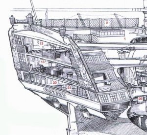
I found this cutaway drawing of the Victory stern. It looks very simple and easy to set up.

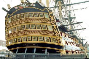
As I was looking on the web, I came across this:

victory stern.jpg
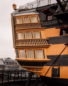
I have to admit it looks hauntingly familiar. It looks like the ST except for a few minor changes and no balconies.

The Victory does not have balconies although some model builders have added them. The designs of the ships of the line were truly an indirect collaboration of Spanish, English, French and Dutch ship builders and designers. In the case of the ST, there are no drawings of the stern so it is anyone’s guess what the stern actually looked like.

At this point, I have no idea if the ST had balconies or not. There was no effort in the kit to show balconies. It appears to be the builder’s choice until someone actually looks at the real ST off the coast of Cadiz and if there is enough of her left to tell.

victory stern-1.jpg
I like the way the Victory stern looks.

stern3-1.jpg
You can actually see the stern windows when you look in the quarter gallery windows.

While I am making a new stern plate, I need to decide if I will put in the balconies or not. To me, the work is about the same. Without the balconies it resolves the stern/window issues nicely. I guess in reality though, one could do the same with the balconies. Looks like it is time for a coin toss to see which way I go.

Later,

Don
 
Last edited:
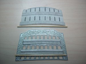
Hi there,

SECTION 2 – Windows & Doors (continued)

Hope this information does not bore anyone but I think if you are going to spend the time, money and effort to deviate from a kit for the sake of historical accuracy, then you have to do some background work. I can tell you I have drawn the stern plate dozens of times now and nothing has worked right. I feel very strongly that the Crespo drawing does have a perspective to it. The math just does not work out.

To resolve this dilemma, I checked out Plan #2, Longitudinal Section, from the Naval Museum of Madrid. I found that the spacing between each deck was approximately the same. I also found the ST did have two balconies. They are very evident in the cutaway drawing. Next I measured the decks on the ST model and found they are approximately the same distance apart. So I feel comfortable with that.

Next I took an outline of the Crespo stern plate. I made sure there was no perspective to the outline. I checked it against the kit stern plate. I then drew a vertical center line and added the location of each deck based on the ST model. The floors to the quarters, galleries and the balconies were just extensions of each deck. Even with the horizontal curvature of the kit stern plate and the Crespo drawing, you can use the vertical center line for the measurement of the windows. Another point, I drew the decks in flat. In real life the decks had some curve to it so the water would run off the ship instead of in the ship. But at a 1:90 scale, they are virtually flat.

The outcome… (I need a drum roll here) none of the window placements matched the kit. Not the stern plate from the kit, the Crespo drawing or even the stern drawing from the museum. No matter how I lined them up, at least one row of windows ended up with the deck edge in the window view.

Believe it or not I am happy with this revelation. I understand the plate with the kit being wrong. Since there is no detail work, the plate works only as an illusion of being correct. The Crespo drawing, I don’t know. It could be correct based on his research but it does not coincide with the OcCre kit. The plan from the Naval Museum of Madrid is probably correct BUT it does not line up with the kit either.

My goal is to morph the kit window size to the Crespo stern plate shape and decoration. I will add in the two balconies and see what kind of detailing I can do with the officer’s quarters and the galleries. It will be fun. At least now I know why I was having such a hard time getting this to work. The template idea I had will work but not as I had originally envisioned it.

My new approach (plan C) will be to cutout the stern and locate the decks. Then I will add the other decks that were not included in the kit. From there I will add the windows, interior walls, furniture (if I can) and finally the decorations to the stern.

Now that I have a plan that I feel will work, I will begin to send pictures of the progress.

Later,

Don
 
Don,
I really think honestly, that you are making the most out of this kit. There are definitely a lot of mistakes on the rigging.

It would be nice if these manufactures would take advice from the builders. Just think of what the kits would be like now?

But, we don't know how many of a particular kit was "cut out" at the same time. Does OcCre even stamp out their own parts or not? I am not sure. Or do they send the parts list to someone else.

I have another modeler friend that built the ST and completed it. I actually talked to him on the phone as he was going over several plates with me and pointed out some rather obvious problems.

He went as far as to write OcCre about some descrepancies on the rigging and was requesting if they had a "revised" plate or plates. Oh, they obliged alright. They sent him another set of plans and plates -- or it might have been the sheet that had the plates on it. Guess what - NO change at all. Seems like the folks at OcCre are out of touch. If there were no changes as far as they knew, then why send a whole set of plans (plates) with the SAME errors ?

I guess the only way to get to them is to have a Spanish speaking friend that can understand the problems we are suffering from this kit and to communicate with the designer - if they have one.

To this day, on the Rigging Plan layout that has all the "numbers" pointing to the belaying points, there still is NO mention what so ever on those two sheets as what to do with the 5 block-double pulleys and 3 eyebolts at the base of each mast.

If you were to follow exactly the belaying layout, you would have such a mess of lines going everywhere it would be a disaster. I really feel for the folks that would attempt this build without any knowledge or any forum to help them.

Donnie
ps. I don't want to shed any negative light against OcCre, but after the ST, I am going to have to try someone else. All I can say is thank goodness for forums.
 
Donnie,

It is hard to say. I can give you my opinion for what it is worth. This may sound like I am defending OcCre but I am not. There is little in the way of detailed drawings on these Spanish ships. That is why they hired people from different countries to design and oversee the building of the ships. . . kinda like corporate espionage. It was the way they did things back then from what I understand. I think that is why there are so many different drawings of the ST with the artist saying “this is what I think it looked like”. It wasn’t until the early 1700’s that that various governments began to set standards and established what they considered to be best practices for building these ships

Even the Mullan's design of the ST was severely flawed. They took a standard 112 gun ship and super sized it. Due to that, she spent more time in the docks than she did in service. She was even nickname “El Ponderoso (ponderous, heavy, weighty or massive)” because she handled so poorly. But when she was in service, you did not want to end up broadside to her for she would surely cut your ship in half. Somehow she has been remembered for her size and guns.

In the case of the ST kit, the only two things you can do are research and use the forums. One, you learn a lot about the period. Two, you develop a lot of friends from all over the world that are willing to pitch their thoughts on it. At the end of the day, you as the builder have to go through it all and say, this is what I think.

Maybe I am off a few degrees but I think I prefer it this way. So the model is off a bit. So OcCre does not respond well. So what! Based on the period of the ship, the practices used for documentation at that time, I don’t think it is realistic to believe a perfect model would come from this. It is my understanding English is taught in the European schools. Many of them can do well in the English camp. OcCre as a global supplier must have people that can speak and read English. I believe the kits are built at OcCre. The issue with any company is do they want to be a good company or a great company. I would not expect them to make changes unless there was documented evidence that their product was grossly off. In a company like OcCre, they may save changes until there are enough to warrant a kit revision. My complaint with them is the lack of instructions and the quality of some of the parts. I agree with you these generalized plates are not good instructions and should be improved. I also believe these kits fit a small niche in the world. I doubt they expected them to be museum quality. Even the ones in the museums are sometimes only what someone perceives the ship to be.

The rigging, for example, was many times done at the discretion of the captain. So you have to figure it will not be well documented. In your case, you have to rely on your instincts and what other people have done. For me the stern has turned into a major challenge. But through careful research, I am beginning to find enough information to give me a fair idea of what she might have looked like. Do I want OcCre to change their kit? Not at all. I do expect them to supply good quality parts and use wood that will not make you crazy when using it. Good instructions would be a huge plus but I can't help but think this is what they call an advanced kit. Perhaps you and I should have started with small tug boats. I have to admit this has certainly been a challenge for the both of us.

What I am doing is only speculation. I have looked at other ships that resemble the stern of the ST, like other Spanish ships of the period and even the Victory. I have made some assumptions and am now working towards that end. I find this fascinating and fun. I hope this makes sense. It is just my evaluation of the hobby. I guess if everything was perfect, it might not be as interesting as it has been for me.

DSC00137-1.JPG
Here is a shot of my stern. I have cut out openings for the officer’s quarters, etc. I have not done any cutting on the hull as of yet. I need to take baby steps on this so I don’t screw it up. I am checking the quarter galleries to see how they might or do fit into this picture.

DSC00138-1.JPG
What I finally ended up doing was taking the Crespo stern I liked and made an outline of it. Then I laid out where the decks of the kit fall (dotted lines) based on actual measurements. Then I added the window outlines. I needed to determine the angles of the windows. From here, I cut out the stern of the ship. As Popeye stated, I will probably have to juggle the windows and rails according to the space available. He is correct on that.

I will have to cut out the gun ports and trim the false keel so I can install the actual keel. I can add the keel and cannon after I get the stern completed. I wanted to do as much of the stern as possible to this point so I could think it through. I am in uncharted waters here.

Anyway, this is what I think. These challenges will make us better and smarter model builders.

Later,

Don
 
Last edited:
All of this may be true since this is of a ship that nobody knows exactly what it looks like. Kits do get revised over time. Hopefully, because of sites like this one, the revisions may become more often and actually lead to better kits.
What has happened in the past, I believe, is that revision only happened when new technology (i.e. laser cutting, photo-etching, etc.) required the manufacture to upgrade if they wanted to stay in business. Unfortunately, some kits were cheapened by this technology such as the one I am working on. Instead of turned stanchions and loss wax casting that the previous Cutty Sark kit had, photo etched stanchions replaced these and some of the casting. Since this is not their most expensive kit, there seems no reason to cheapen this kit. Quality, not price should have been the issue. It seems that a better kit would be a big boost to any manufacturer.
 
Gary & Popeye,

This is a sad state of affairs gentlemen. These kits seem to be going by way of most things in this world. Steel cars to plastic, everything modular or automated and all for progress and profits. Shoot, they are trying to make the "terrible lizard", the dinosaur, into a big bird on steroids. Old arts like stone carving, hand tooled this and that are now automated, if done at all.

So that leaves the authenticity of these ships to the builder. It is ashame. Model building has been here since man learned how to put two pieces of anything together. Guess that is why there are many scratch builders out there now. You end up making or buying the retro parts anyway.

I am new to this hobby and by accident have managed to make the best of a bad situation. You have watched me stumble through this process. All I can say is when my ST slides off the skids, it will be as close to the original as I can determine. It will be something I put time and effort into and something I did with my own two hands. I will probably know more about 18th century warships than I needed to know. I will know more about the people of that time and more about naval warfare in general. All in all, it seems like a win-win for me.

I am disappointed that these manufacturers continue to cut corners for a profit. In the long run, they are only hurting themselves and the hobby.

Well, on to cutting out my cannon ports, trimming the false keel and thinking about the stern.

Later,

Don
 
This is the true reward. You do end up an expert by the time you study and learn the vessel. This not only improves the current vessel, but all future projects.
There is a lot of manufactures out there that are making a lot of different fittings. Because of this, the right fitting for what you are making may be made by another manufacturer. I have been able to do this on several models.
Good luck.
 
Hey there,

Did you ever get one of those ‘aha’ or ‘I should have had a V8’ moments while working on a model. I had one and thought I would share it with you. I think by now it is a well known fact that the cannon port placement on the ST is not as good as it could be. For whatever reason, I was having a problem trying to figure where the cannon ports should go. I bought some ship’s curves and was going to use them. With all the twists and curves on the hull, however, it did not work as well as I had planned.

Then one day it hit me. Above all things, the cannons have to sit on the deck. As with the stern, if I know where the deck is, then I know where the cannon ports should be. I know this may sound lame but it never occurred to me to think of it this way.

What I originally did on the ST before planking was to mark a center point for each cannon port on the bulwarks. Then I made a spreadsheet, and measured and recorded the distance between each port. I also measured and recorded the distance from the top bulwark to each cannon port.

When I started planking, I opened one port for each deck so I could see the center mark. From that point forward, I did not cut any other ports. Once the planking was completed and sanded, I started with the 3rd battery deck. I made certain that the original center mark was in fact in the right place. I did not worry about the main deck as I could see where the port opening went.

From this point I took my measurements and marked where the original center mark was for the horizontal plane. For the vertical measurement I used the distance between the first center point and top bulwark. I used this measurement instead of the measurement I took before planking. Doing it this way, I maintained the contour of the deck and therefore the proper height of the cannon. I made a crosshair mark at each concealed cannon port. Then I made a template of the correct size for the port. I centered the template on the crosshair and marked it. From there I opened the port.

When doing the second and first batteries, I measured the distance between the decks including the thickness for a deck. I used this measurement for the horizontal plane measurement. I have to tell you, the cannon ports came out perfectly. As I opened up each port, I could see my original center point. Some were off quite a bit.

I hope this does not sound complicated. It was very simple to do and made the planking process pretty straight forward. I have one side of the ship almost completed. As soon as I get the ports cut, I will take some pictures. One thing I found, the OcCre kit was missing about 18 port frames. I also found about 8 of them that were formed wrong. 2009, when I bought this kit, must have been a bad year for the OcCre folks.

Anyway, wanted to share this and my progress.

Later,

Don
 
Hello,

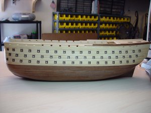
As promised, here is one side of the ST with the 1st, 2nd and 3rd battery ports opened up.

DSC00140-1.JPG
If you remember in my last post, I mentioned I left a port on each deck opened during planking so I could use it as a reference point for the other ports.

DSC00141-1.JPG
This is what that looks like for the 1st, 2nd and 3rd battery decks.

I must admit I am really please how this turned out. It is truly a lot of work since there are 52 ports of this style to open on one side. But with careful use of a Dremel, it does make it go faster than trying to open it with a #11 x-acto. I will have to tweek a few of the port frames when I install the rubbing strakes but for now the placement for the ports are correct.

Well on to the other side of the ST and then the keel trimming. After that, back to the scratch stern build.

Later,

Don
 
Last edited:
jct,

Thanks much. I even surprised myself. I am learning very quickly that laser cutting and computer programming does not necessarily mean it is correct. I am beginning to believe more and more that the kits are just an illusion. It is up to the builder to bring it closer to reality. It is very rewarding to see this thing begin to turn into a thing of beauty from this pile of wood, metal and cords.

Well, 52 more of these ports to go. Then 42 of the main deck ports and finally four in the stern.

Thanks again.

Don
 
Back
Top