Endurance 2nd build

Glad someone else tried out the blob of clay method of ladder construction!

You ran into the same problem I did with the cost of stanchions. Glad you found a more reasonably priced source and I look forward to what they look like. I am still not very happy with the way mine turned out. I did make a solid brass rail at the back of the forecastle which I liked a lot better than using thread.
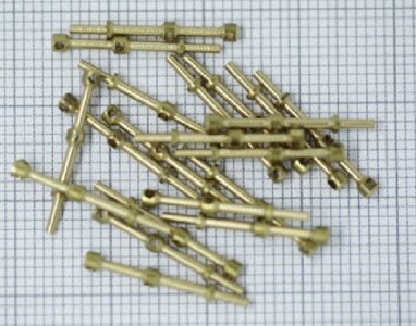
I fear that stanchions that I have coming may be a bit over size at 17mm, although I think that includes the bit below the surface. So probably 13/14 mm from the picture they give. I think I can live with that.


Screenshot_20220909_175713.jpg17€ shipping but still just over 41€ for 80. It looks like they take up to 1mm wire but I'm not banking on that until I have them in my hand! The rail around the stern looks to be wood in the photos that I have seen, indeed the famous underwater photo seems to confirm that so I will be attempting to replicate that somehow. I hope my new stanchions will work there as well.
 
The Billing Boats stanchions arrived yesterday, almost a week before they were due so I'm able to get on with finishing the deck fittings and fit the railings. They will take wire 0.8mm día ( not 1mm) which I can get at my local Chinese bazaar (we have more than 10 within a spit of here), galvanised, for 4.50€ a coil.
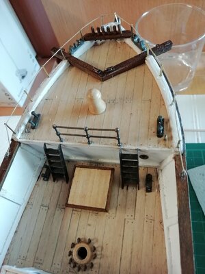
I had at trial run with the handrail at the rear of the foredeck using the brass rail supplied for the sled runners. IMG_20220917_142238.jpgA touch oversize according to Occre but looking at actual photos it seems to have been about 3 ft (13.5mm to scale). The BB stanchions are exactly that. Screenshot_20220917_155922.jpgSo of to the Chinese shop and continuing with the deck fittings....
 
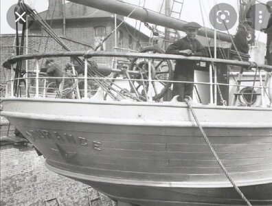
Hello Very good photo of the crew of the Endurance in the bow. I want to make this boat when I have time and it will help me
Thank you and regards
 
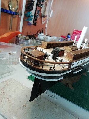
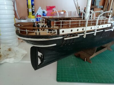
The kit uses the same method for the stern rail as for all the other railing. Now we have all seen the underwater and other photos it clearly was not like that in reality so I have attempted to get closer to the original.
Screenshot_20220917_155846.jpg
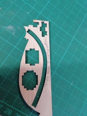
Fortunately, for once, I had the forethought to save the cut out of the stem deck edging and was able to use that as a template for the hand rail. IMG_20220918_145647.jpgUsing 2x2mm, i was able to bend four pieces in this shape and glue them in pairs so they held the curve.
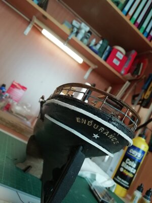
I'm quite pleased with the result, or at least a lot happier than I would have been with the kit-supplied arrangement. IMG_20220918_144623.jpgIMG_20220918_144610.jpgPerhaps the colour is not right. What do you guys think?
 
Hello Very good photo of the crew of the Endurance in the bow. I want to make this boat when I have time and it will help me
Thank you and regards
Thanks, Llaut.
There are a lot of photos to be found on the Internet and in books which makes this such an interesting build, for me anyway. You'll enjoy your Endurance too, I hope.
¿Donde en España estas?
 
Thanks, Llaut.
There are a lot of photos to be found on the Internet and in books which makes this such an interesting build, for me anyway. You'll enjoy your Endurance too, I hope.
¿Donde en España estas?
Hello Barcomad
I live in Guadalajara 55 km from Madrid
And you?
 
Hello Barcomad
I live in Guadalajara 55 km from Madrid
And you?
I live over on the east coast, in Vinarós. Its the last town in la Comunidad de Valencia, just south of Cataluña.
My nearest model shop is in Castellón, 80 km away. You are probably better served being near Madrid.
Happy modeling...
 
In Madrid there are still some physical modeling shops.
In Bilbao he closed Hobbies Guinea, which had it all...
I usually buy online
Cheers
 
Continuing with the railings:
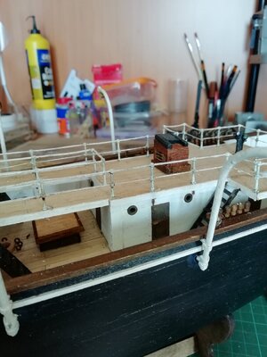
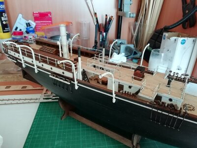
I decided that the secondary stern rail should be white so painted it and later treated it with the betún de judea to age it.IMG_20220922_155742.jpg The side rails on the upper deck and those around the ínterior of the deck cabin roof were possible using the 0.8 and 0.5 wire that I bought. The exterior of the cabin roof however proved too difficult for me to fit around all the corners and get a neat finish. It looked awful. So I used the 0.5 and 0.15 thread, soaked in cola blanca glue then, once in place stiffened with CA glue. Painted and aged, it came out OK. IMG_20220922_160311.jpg

IMG_20220922_155715.jpg
 
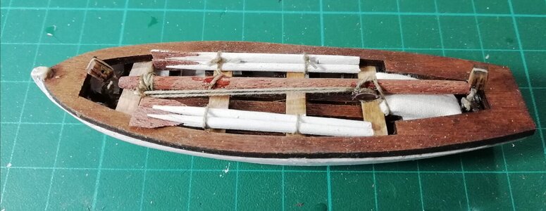
After a break of a couple of days I've started on the small boats. I found it quite a challenge for my clumsy fingers but after several hours of struggle I achieved an acceptable result. I decided to enhance the kit version with some oars, a mast and a bag of sails. Not sure of the authenticity of this but I like the added detail. IMG_20220929_160748.jpgNow for the other three...
 
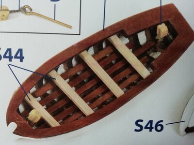
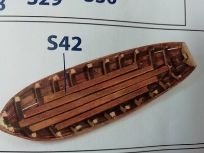
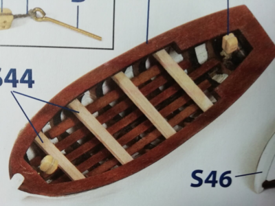
One of the challenges in building the small boats is that the finished picture (and the video on YouTube) show the deck boards with large gaps between as would be necessary in reality :
IMG_20220929_161312.jpgToplace 5 x 3mm wide boards like this is impossible. In fact the previous picture shows how the gaps are not possible even when the outside boards are put at an angle:IMG_20220929_161305.jpgI eventually overcame the issue by trimming 4 of the boards to 2mm wide. The central one had to be left at 3mm in order to fully cover the keel.
 
Good evening
There is a "historical" mistake in many kits and that is to make the floor of the rescue boats, with slits between the bottom boards.
Let's think a little about the purpose of this form of construction;
Break an ankle when the sailor goes barefoot?
Fill the bottom of the boat with garbage?
Losing easy an object that is difficult to recover since you have to remove the entire bottom of the tables?
I say this because I had a boat and the bottom was also sectored ("panas or panels" they were called), and they was together.
I really don't see the use of it ...
Please someone explain it to me.
Cheers
I thought it was so that the boat could take on some water without the sailors having have their feet constantly wet. But I have no basis for that idea, I'll try to look it up.
 
I had a boat and the panels let water in and out where they meet the ribs.
When we caught any small fish, we caught it before it slid to the side to prevent it from sitting under the panel and rotting.
Periodically they had to be disassembled (by sectors), to clean the crap from the bottom.


Your boat is doing very well.


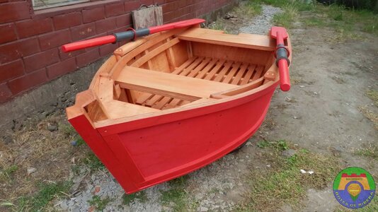
All classic boats do not have grooves on the bottom floor, however, in modern boats, they may be put to prevent people from slipping
Icono de Validado por la comunidad


Abrir en el Traductor de Google

Enviar comentarios

Traductor de Google


BOTE PESCA.jpg

BOTE MODERNO.jpg
 
Last edited:
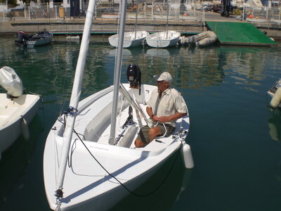
My 5m sailing dinghy had A GRP hull and deck so I have no personal experience only that once we were up to speed we sometimes had to take out the bung in the stern to let out the accumulated water.CIMG0978.jpg
 
Hello
If the water inside the boat can only be evacuated by pump or by hand.
On a small boat, that manual labor should be easy to access.
The panels must be easily removable and sectorized, they can never be fixed or go from bow to stern.
You have a nice pleasure boat
The stern plug should be above the waterline...
Cheers

1664533828400.png

1664533849168.png
 
Last edited:
Hello
If the water inside the boat can only be evacuated by pump or by hand.
On a small boat, that manual labor should be easy to access.
The panels must be easily removable and sectorized, they can never be fixed or go from bow to stern.
You have a nice pleasure boat
The stern plug should be above the waterline...
Cheers

View attachment 331392

View attachment 331393
I sold the boat 7 years ago. We had not used it for some time as my wife was very ill. She eventually died and I lost all interest in sailing. I never was that keen and only learnt to sail when I moved to Spain in 2009. The seas here are not so good for a novice sailor, either no wind and extremely hot in a small open boat or too windy to be enjoyable. At the age of seventy I also lacked the flexibility and athleticism to handle a small dinghy in anything but a calm sea.
I since remarried but my new wife can't look at a sailing boat without being sick!
So sailing now confined to modelling, the occasional cruise and the ferry to the UK.
 
Funny how little details can take up so much time and thought...
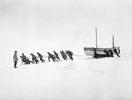
I had some left over thread so, as I normally do, I made a couple of hanks of "rope" to put around the decks later as an embellishment. I put one beside the sleds that I had made earlier as per the instructions and realised that the sleds were far too small according to scale. At 20 mm they would have been only 1.4 metres long, photos in Alfred Lancing's book and elsewhere show them much larger, nearly half the length of the small boats:Shackleton-Antarctica-endurance-photographs (31).jpgimages.jpeg
So I tried to make something larger (4cm) and more like the images that I found.
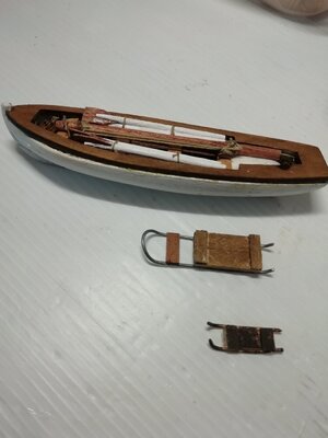
For comparison I show one of the small boats, one of the larger sleds that I made and the one I made to the instructions. IMG_20221013_174416.jpg
Where to situate them on the model is a decision for later as they now do not fit where suggested in the instructions.
Enough procrastination, now for the masts...
 
Not the first mistake and almost certainly not the last...
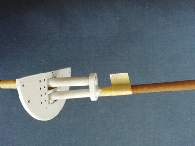
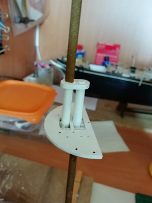
I set the platform on the fore mast shown as b9 in the drawing with the rear edge 4mm back from the mast which meant that the internal edge was again the mast. When I fixed the upper mast it was not parallel with the lower. IMG_20221017_114907.jpg
I had to take it apart and reset it with the platform (correct term?) edge 6mm from the mast. Now it is parallel:
IMG_20221017_171257.jpg
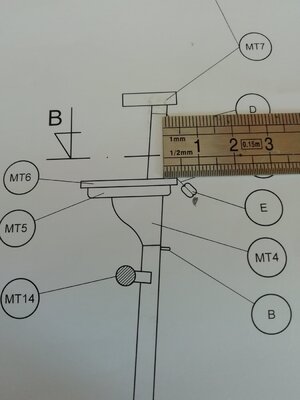
I was kicking myself for not checking the drawing but then discovered that the drawing shows it the way I had it at first:IMG_20221017_172908.jpg
I haven't seen any other builders of the Endurance making the same error so maybe my lack of experience or brain cells is the cause.
I'll be looking out when I make the next two masts.
 
Back
Top