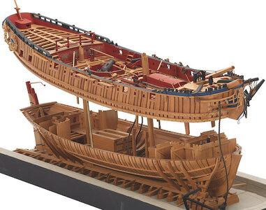
H.M.S Granado. Plank on frame 1/48 scale. CAF model.

Hello Uwe,
I do not want to interrupt Brian's answer, but I did find out some info that I share on POST #114. I am sure that Brian will like to have the opportunity to respond - sorry Brian if I answer too soon for you. Please elaborate if you wish.

Hallo Donnie,
thanks for the hint, but the principles are clear for me. I asked where would be the area of the frames, looking at the framing of Brians model, and not on a single frame

Hi Uwe and Donnie,
I was considering building the frames without a separation, then cutting through them with a Dremel diamond disc.
Not sure whether it will work, but previous experience has been good using this diamond disc.

.View attachment 292557
Yes, I understood, that you will do it different than prepared by CAF - with a saw you can cut where ever you want...... but where is the "line" if you would follow the CAF kit design. Is the red line appr. correct in my photo? I would like to get a confirmation on my thoughts.
I am interested in this, because I am thinking about trying this solution on my model....
 
Hi Uwe,
I was thinking about cutting the separation line through the frames under the wale like the original ship model below. I think its an easier option and looks neater.

.
View attachment 292816

My thoughts exactly - looks much better, and is what I intended from the start.
Not yet decided on whether to use a cutting disk or a fine-toothed saw - will be carrying out some experimentation nearer the time.

Ted
 
Good to see an update on your work on the Granado - we waited a longer time for it.
Would be happy to see more often some posts showing the work and the way you do it ......

One question:
As I understood, you are not preparing the frames with the possibility of separation the top from the bottom of the hull.
But in principle, where would be the dividing line appr.? Am I correct with the red line?
View attachment 292438

Hi Uwe,
I think you are about correct with the red line, but feel the absolute position would be better dictated by the level of the wales on the outside of the hull.

Ted
 
So, now, I am also intrigued. Isn't there a line on the drawings as to where the separation occurs? (even though the picture shows the separation right below the Wales)... Also, I would think there should be a scribed line on the frame pieces.
 
Hi Uwe,
I was thinking about cutting the separation line through the frames under the wale like the original ship model below. I think its an easier option and looks neater.

.
View attachment 292816
If you glue on the wale you have a guide where to cut and more accurate
 
I won't know for sure until I have part 3 in hand but right now it looks like the separation has to happen where the existing upper joints are in each frame. There are no scribe marks for making a cut. As designed, when the upper part of the hull gets lifted, the upper point of the joint half comes up with it and the lower part of the joint tooth stays with the bottom of the hull. The joints in question are the ones that CAF recommends holding in place with wire vice glue in the early stages of the build. The various inner and outer wales that get installed during the build bracket this joint area quite nicely. Hope this helps
 
Hi guys,

my next project just arrived today. Its the new kit from Tom at CAF model in Shanghai China. It arrived at my doorstep in 7 days from ordering it, and that is excellent mail order service.
This is the full hull version, as there is also a cross section kit of this ship available. The first stage of the kit features all the frames which are very accurately laser cut in Cherry wood and also includes the building cradle.

Here is the two boxes of the first stage -
Hallo Brian,
also from my side
we wish you all the BEST and a HAPPY BIRTHDAY
Birthday-Cake
I hope also, that you are able to show in some time more progress on your Granado
 
Back
Top