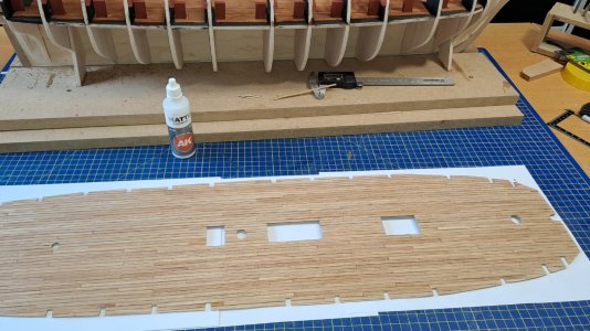
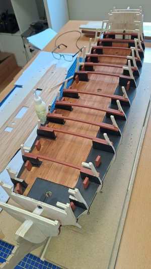
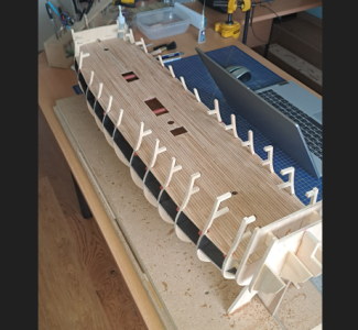
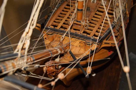
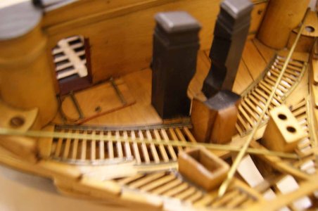
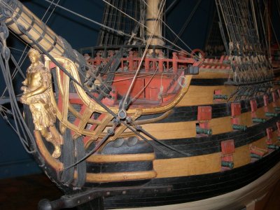
Very clever approach on the gun deck!And now for the bottom gun deck. There was no way to fit the bottom gun deck in its entirety. So I cut the deck in half. To hide the seam, I made sure a strip extended 2 mm beyond the cut edge...so I could slide the second half in seamlessly later.
View attachment 532041
View attachment 532036
View attachment 532037
View attachment 532038
View attachment 532039
View attachment 532040
-

Win a Free Custom Engraved Brass Coin!!!
As a way to introduce our brass coins to the community, we will raffle off a free coin during the month of August. Follow link ABOVE for instructions for entering.
-

PRE-ORDER SHIPS IN SCALE TODAY!
The beloved Ships in Scale Magazine is back and charting a new course for 2026!
Discover new skills, new techniques, and new inspirations in every issue.
NOTE THAT OUR FIRST ISSUE WILL BE JAN/FEB 2026
You are using an out of date browser. It may not display this or other websites correctly.
You should upgrade or use an alternative browser.
You should upgrade or use an alternative browser.
HMS Agamemnon by Caldercraft
- Thread starter HMSFly
- Start date
- Watchers 32
-
- Tags
- agamemnon caldercraft
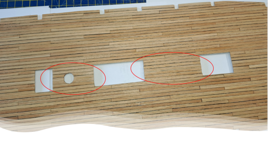
Dear Iutar,Dear Fly! There were no planks with joints between the hatches. Why lay pieces of wood if you can lay a whole plank? The principle of sound logic and technical perfection is at work here. Short pieces and splinters will break quickly. And why put short boards, because there are plenty of normal boards at the shipyard?!
No planks were spared for the deck. We have already discussed this on Diana.
View attachment 532042
You have shown the joints in other places incorrectly. You should have found a drawing of the deck beams. But if there is no drawing, the beams can always be calculated by the hatches: the hatch coamings were always laid on the beams. The joints of the boards had to lie on the red lines.
The deck is half the impression of the model. You can't rush here. It's not too late to fix it.
View attachment 532043
I've searched like crazy trying to find accurate information about deck planking. I even contacted very experienced specialists and received the response that there weren't/aren't any clear guidelines.
I didn't think this was a topic for the Gun deck, since you barely see anything of the deck anyway...
But for the main deck, it's a different story. I'll try to implement it as faithfully as possible. But what did the main deck planking look like? I'd appreciate your clear guidelines.
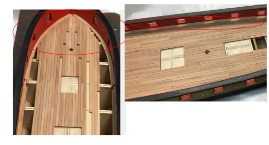
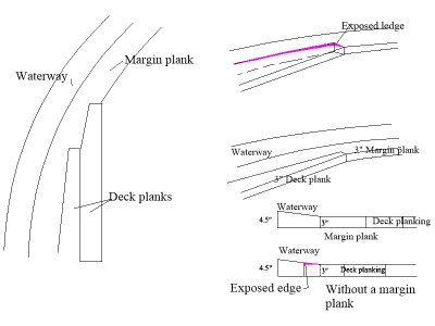
Question for Iutar and all your followers. Were the deck planks joggled into the waterway or was there also a margin plank fayed to the waterway which was cut to receive the joggled planks? If the former, there would be ledges where the planks fay to the waterway.
Also, were the outer strakes of planking on the upper deck plain sided, anchor stock or top and butt? There is no mention in the contract of this so I am assuming it would be plain sided.
Excuse the poor sketch, but it is hard to convey my thoughts to paper The dimensions are from the original contract.
Thanks
Allan
Also, were the outer strakes of planking on the upper deck plain sided, anchor stock or top and butt? There is no mention in the contract of this so I am assuming it would be plain sided.
Excuse the poor sketch, but it is hard to convey my thoughts to paper
Thanks
Allan

Last edited:
I've searched like crazy trying to find accurate information about deck planking. I even contacted very experienced specialists and received the response that there weren't/aren't any clear guidelines.
I didn't think this was a topic for the Gun deck, since you barely see anything of the deck anyway...
But for the main deck, it's a different story. I'll try to implement it as faithfully as possible. But what did the main deck planking look like? I'd appreciate your clear guidelines.
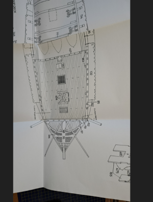
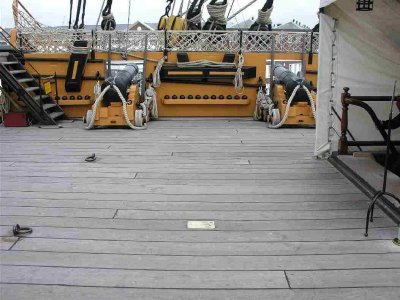
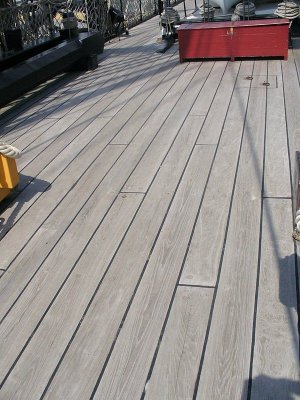
Of course, there are instructions. Here are the original drawings. Look closely and you will see the joints of the boards at the bottom. The other joints are not shown so as not to clutter the drawing. They can be restored with a "ladder". There are almost no joints on the poop and forecastle decks because the length of the boards was sufficient. Also note how the boards are cut into each other.
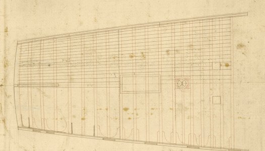
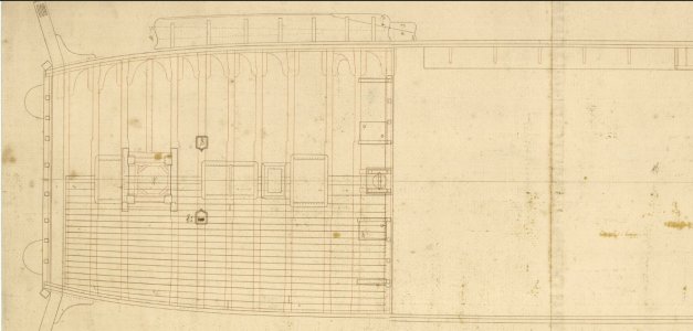
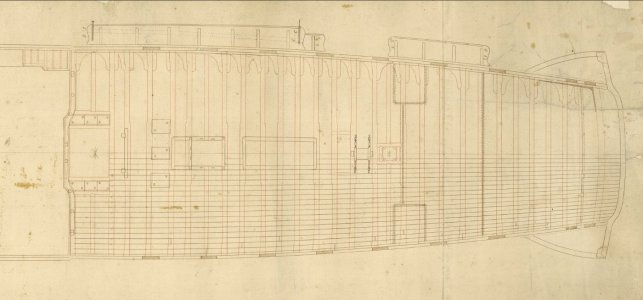
"Ladder":
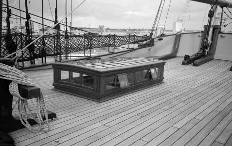
Dear friend, it takes a long time to answer, to look for pictures and drawings, and I already have to run to work. If you don't mind, I'll answer later, maybe the day after tomorrow.Another question Iutar,
How would you plank these decks?
These are great drawings Iutar. Can you tell us what ship/year/nationality this ship is?Here are the original drawings
Thank you
Allan
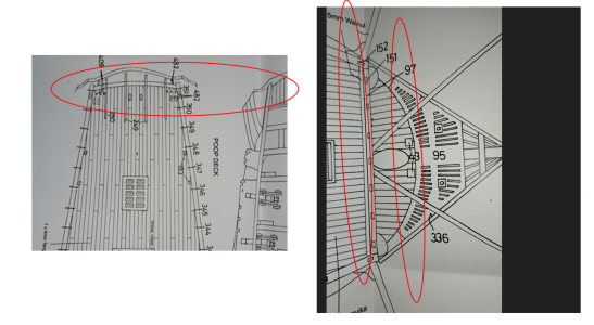
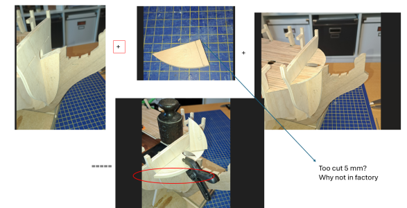
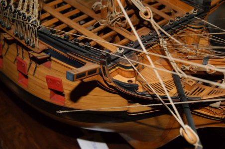
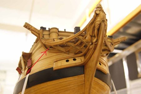
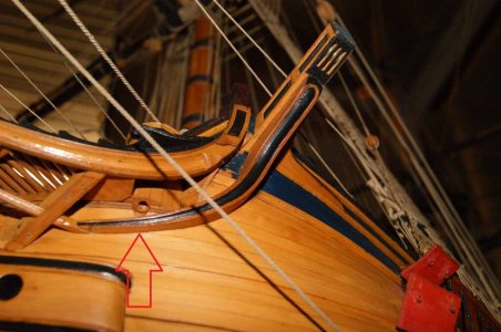
Hi Marc,why doesn't this bow piece fit?
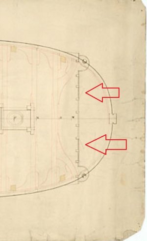
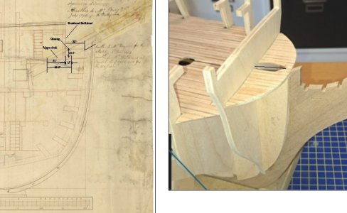
Is it in the right place? The below shows both the extension of the gun decking under the beakhead bulkhead and what looks like what may be some type of platform/grating above it. Look at the opening through the gun deck and beakhead bulkhead for the sprit on the drawing below. If the drawing with the dimensions is not clear, give a shout and I will try to zoom in on the dimensioned area.
Allan
Last edited:
Ah, ok.Hi Marc,
Is it in the right place? The below shows both the extension of the gun decking under the beakhead bulkhead and what looks like what may be some type of platform/grating above it. Look at the opening through the gun deck and beakhead bulkhead for the sprit on the drawing below. If the drawing with the dimensions is not clear, give a shout and I will try to zoom in on the dimensioned area.
Allan
View attachment 532613
Could you please zoom out in your drawing..it's not clear for me.
Thx
Marc
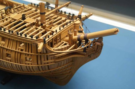
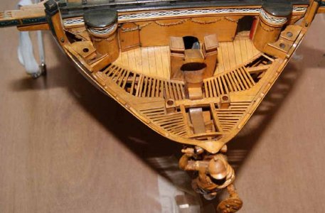
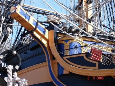
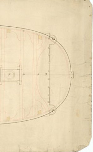
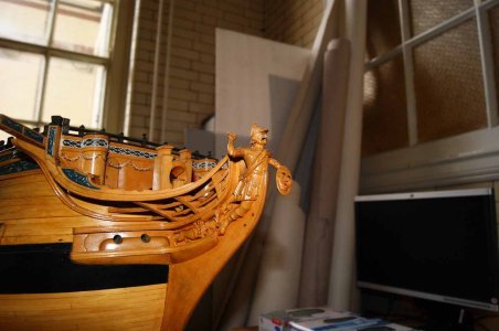
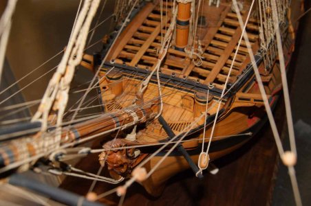
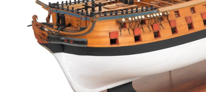
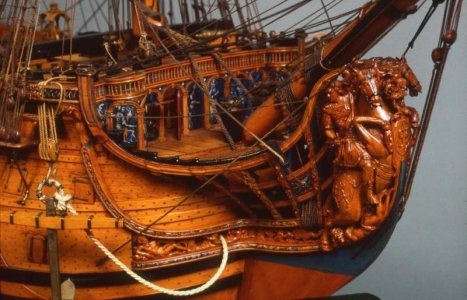
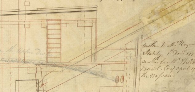
Allan, I have a larger version of the fragment. This upper deck of the hullhead was intended to protect the heads of the hauspieses from water. This deck had no camber or slope, was parallel to the waterline but not parallel to the upperdeck, and was used only on ships designed by Sir Thomas Slade.
During the late refit of Victory, this bay deck was restored.
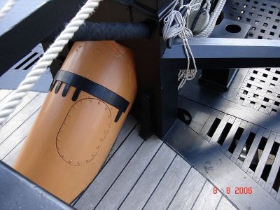
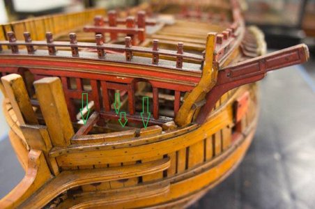
During the late refit of Victory, this bay deck was restored.


Thx Iutar,
So if I understood it, I have to cut 5 mm and glue tje peace as support for the small deck?
Marc
Iutar, your collection of photos of contemporary models is incredible!
Marc, I still question the opening for the sprit through the deck. It does not match up with the contemporary drawing. It may be the angle of the photo, but it does not look like the sprit can rest on the top of the stem and still go through the opening as indicated in the contemporary drawing. It's as if that portion of the deck is too high or the stem is too low. Something definitely amiss assuming the original drawing is correct. I am very curious to see how this is resolved.
Allan
This is a drawing from the Greenwich collection, showing an English unattributed 'typical' third rate ship, circa 1770s.These are great drawings Iutar. Can you tell us what ship/year/nationality this ship is?


