HMS Alert [1777] 1:48 POF by serikoff. (Two hulls: skeleton and fully rigged)

an example is this painting by an artist appointed by the admiralty : https://en.artsdot.com/@@/9DHL9Q-Thomas-Buttersworth-

my guess is that they would not reef the main square sail when sailing downwind, but if sailing close hauled they would feather it to provide minimal disturbance to the fore-and aft sails and they would reef it up. As far as the proposal to display the model with all sails set, that is fine, but it would be neat to reef the main up about half height.
 
Last edited:
While I like the image of the ship with all sails raised, I don't think that's a realistic conformation. The sails would surely choke each other? I imagine that Alert would either use the fore and aft sails with a beam wind or the square rigged sails with a following wind, or varying combinations according to circumstances, but never everything at once.
I don't think so. Of course, when there was a strong wind, the upper and lower square sails were removed, but when there was little wind, not only all the sails were set, but mattresses and tablespoons were ready to be set downwind, just so there would be some movement. So, when there was little wind, all the sails - that's for sure.

Serrikoff,
you are a brave soul, and I wish you luck. I have built the kit, and it is an impressive piece of computer aided design. The fully rigged ship will be impressive. Worth mentioning that the hulls of naval cutters of that era were clinker planked. It will be interesting to see how you will translate a 3D image of the hull "in-frame" to a clinker-built hull.

good luck Thumbs-Up


I don't think that is correct. There were many ships sailing with 'fore-and-aft' sails plus 'square sails', and that includes naval cutters.
Thank you. I have already thought through the idea with the casing, how to implement it. It is difficult to explain, but if it comes to that, you will see everything yourself, I will show it in detail)
 
an example is this painting by an artist appointed by the admiralty : https://en.artsdot.com/@@/9DHL9Q-Thomas-Buttersworth-

my guess is that they would not reef the main square sail when sailing downwind, but if sailing close hauled they would feather it to provide minimal disturbance to the fore-and aft sails and they would reef it up. As far as the proposal to display the model with all sails set, that is fine, but it would be neat to reef the main up about half height.
The upper and lower square sails were either set entirely or removed. The lower square could be reduced by 1/6 but this did not significantly reduce it. There are no ropes for the sailors' feet on the yards of these sails, so they were lowered. The lower one on the hull, the upper one to the middle yard which had ropes for the sailors' feet.
 
So, now let's talk about the wooden materials from the set in more detail.

Let's start with the details of the frame. All of them are placed on 4 large (M7, M8, M9, M10) and one small plate (the last one below in the photo, M11).


From all these parts a slipway is assembled, in which almost the entire hull of the ship is assembled.


Previously, there was nothing like this in the kits and everything had to be assembled on the knee and the result was corresponding. I am very glad that progress does not stand still and manufacturers make life easier for modelers.
_______________________________________

Next are the plates with conductors.

These plates, as details of the slipway, are not made of solid wood, but of pressed wood chips (fiberboard), but quite strong. Below in the photo is a plate (M11) from the slipway kit, M12 is a conductor for assembling the keel and the rest are conductors for assembling the frames.


In general, nothing complicated. M12 is a veneer in which the contours of the keel parts are cut out. By the way, in the first sets this jig was not made of veneer.


When assembling the original parts, they must be adjusted and inserted into the appropriate places of this jig. Very convenient and practical!

With plates M1, M2, M3, the situation is similar. They are needed for the correct assembly of frames and giving them the correct profile.


_______________________________________

The situation is completely similar with plates M4, M5, M6.


Some still have fragments of the slipway.


On others there are retaining clamps.


And on the M13 plate there are conductors, along which the frames are cut and the line of the barhouts, etc. is drawn. It, like the M12, is made of veneer.


The manufacturers have really gone to great lengths with all these devices and this greatly simplifies the assembly of the model! Not only does it simplify, but all these "Jigs" allow you to do everything clearly and accurately, which reduces the chance of errors accumulating that appear at the very beginning.

I briefly ran through the wooden parts that will not be on the ship, but without which it is impossible to assemble it... And below I will tell you in more detail about those that the model will consist of. This is what "The Ship. The Beginning" looks like )))


...
 
And these are already plates with parts from which the ship will be built.
The arrangement of parts (template) differs from the review that is already on the forum. Below I will post a photo of the instructions with part numbers. And at the same time I will briefly describe my impressions of the set, pros and cons.

№1, №2, №3, №4.


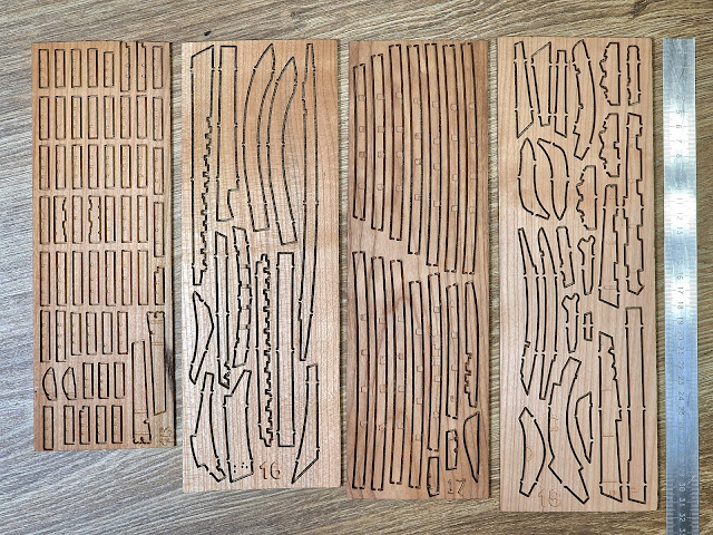
Cherry wood slabs, slightly more than 4 mm thick and dimensions +-10x40 cm.

The wood is good, dry, smooth and without knots (in places of parts). Milling without visible defects and marriage (this will concern all blanks.) But I want to note that there were such moments.


That is, there was still a defect, but all the defective parts were replaced with whole ones and glued into the appropriate places with tape. I did not find any damaged parts that were not replaced. I don’t know, maybe this is the case with all sets, but this set is from AliExpress and accordingly the price may be cheaper because of this. Although, if all the defective parts were replaced, I don’t see this as a tragedy.

The second point is dust and sawdust from the cutter. Probably, depending on the density of the wood and the sharpness of the cutter, the sawdust was held differently in different parts. From some plates it was possible to extract sawdust with a vacuum cleaner, and from others it was difficult even to scrape it with a metal needle. (I will tell you more about this later).


№5, №6, №7, №8.


Similar to the first 4m, these are cherry wood plates, 4mm thick and measuring +-10x40cm.

Continuing with the topic of sawdust after the milling cutter, after removing it, the cut ends are visible differently on different workpieces. On some, they are smooth, like after a knife, while on others they have villi, which will require additional grinding to get rid of this "wool".


Replaced parts are still found instead of defective ones.


And one more inevitable moment is the difference in wood color.


And I'm not talking about the halftones of brown. This is where the details differ and create the effect of the multi-component nature of the entire ship model. I'm talking about the specific white areas of wood that will stand out significantly from the rest. But I have an idea for this, to use water-alcohol wood stain to tint these very light areas. I'll experiment on samples and I think I'll get a good result.
 
№9, №10, №11, №12, №13.


All the plates have the same parameters, up to 4m thick, but the 12th is short and there was another one with semicircular parts, which turned out to be defective on the 13th plate.


It's nice that this defect was replaced and a new set was given, as well as the part in the photo below.


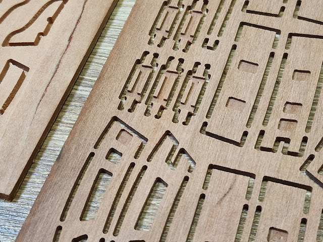
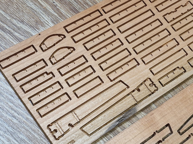
And we are smoothly approaching the most important difference between the kit from AliExpress and the drydockmodelsandparts website. This is the method of milling the blanks! The first 12 plates differ not only in the different positioning of the parts, but also in the cutting method. The 13th part is milled along the entire perimeter, but the last 0.5 mm is not cut to hold it in place. This is how all the parts from drydockmodelsandparts are made. And in the kit from AliExpress, only parts from the 13th are made this way, and from the 1st to the 12th, the cutting method is as shown in the photo below, on the right.


That is, the part on the plate is cut through, and several holders are left that hold the part. Which, by the way, simplifies in most cases the removal of sawdust. And also, the plate with #14 is not in the set, as well as in the instructions, as well as in other sets. It simply does not exist. Well, okay, 13th, here at least it would be logical, but 14... but as it is)))
 
№15, №16, №17, №18.


But starting from the 15th plate, everything is a little different from the previous ones. In order.

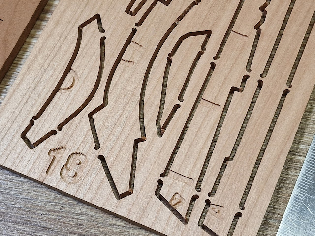
Firstly, they have a different thickness. No. 15 - 4.3 mm; No. 16 - 5.2 mm; No. 17 - 5.1 mm; No. 18 - 5.2 mm.

Secondly, all these plates are double-sided, i.e. milling occurs on both sides.


In the 16th and 18th, grooves are cut for horseshoe-shaped hinges on both sides.


On the other two, grooves are cut in the beams for perpendicular partitions.


Which will greatly simplify the assembly process and the correct positioning of the parts.

And the only thing that upset me a little is the plate with the keel parts.


It's hard to explain, but the angle at which the plates are cut does not show the structure of the wood very nicely. The fibers do not go lengthwise, but rather diagonally, creating a pattern... I also call it a "fish eye". I will still check how it will look under oil and bitumen, and in theory under a little stain, but it is what it is. Another point is that if I make a second case, as planned, these parts will be tedious to make again. Therefore, I will return to this issue.
 
№19, №20, №21, №22.


Like the previous ones, these plates are also slightly different.

Firstly, they have different thicknesses. No. 19 - 3.4 mm; No. 20 - 2 mm; No. 21 - 3 mm; No. 22 - 2 mm.

Secondly, they also differ in the milling method.


They have all the same defective parts replaced.


Still, some have light areas and on plate 22 there are a number of parts with a cut not only through, but also to a certain level. And as you can see in the photo, there are a lot of chipped thin areas. And now, it is difficult to judge, but I am afraid that this will affect the accuracy of the fit of the parts and the appearance of cracks, but I may be wrong, practice will show.


And if we don’t take into account the above, and those defective parts that the manufacturer replaced, then the only part that was damaged was this one.


But it is also located inside and will be covered on all sides, so for now everything is fine.
 
№29, №30, №31, №32, №33, (№34), №35.


I signed parts #34, #36, #27 and #38 myself to indicate their thickness. And here is also M14 - to make for positioning (jig).

29 - 2.4 mm; 30 - 2.1 mm; 31 - 2 mm; 32 - 2.5 mm; 33 - 1.2 mm; 34 - 2.3 mm; 35 - 2 mm; 436 - 2 mm; 37 - 4.3 mm; 48 - 2.6 mm.

Here, I will not repeat myself, everything is the same: something is milled, something is cut on a laser. But everything is still in good quality.


Details that I have signed myself for convenience.


There were also several more wooden parts in the general set.


These are deck slats, cylindrical blanks for the mast and slipway, a bowsprit blank and several rods of brass wire.


In the box with the metal there were also wooden deadeyes and pins for rigging, as well as a rope for the anchor (which I didn't really like).

That's all for the wooden materials.

As for the metal parts, they are completely the same as in all the kits. I didn't unpack them, but after visually comparing them, I didn't find any differences. During the assembly process, I will take detailed photographs of them before and after processing and blackening. Here's where you can see them.


As a conclusion, I want to answer that I am very pleased with the set. I do not yet know what nuances there may be during assembly, but visually the set is very "rich" and I am very glad that I bought it.

Ship-1
 
Last edited:
Сергей привет! Буду следить за постройкой, удачи!!! Я и у тебя на сайте был когда он еще был рабочий до всех событий.

Sergey, hello! I'll be following the construction, good luck!!! I was on your site when it was still working before all the events.
 
Last edited by a moderator:
Sergey, hello! I'll be following the construction, good luck!!! I was on your site when it was still working before all the events.
Технически он и сейчас рабочий, но форум умер(( Спасибо. Но я ещё частично заканчиваю первый проект, потому скорость будет черепашьей))

Technically it is still working, but the forum is dead(( Thanks. But I am still partially finishing the first project, so the speed will be snail's))
 
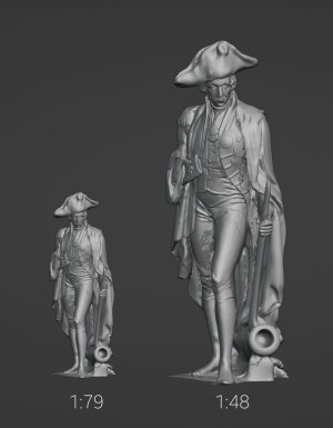
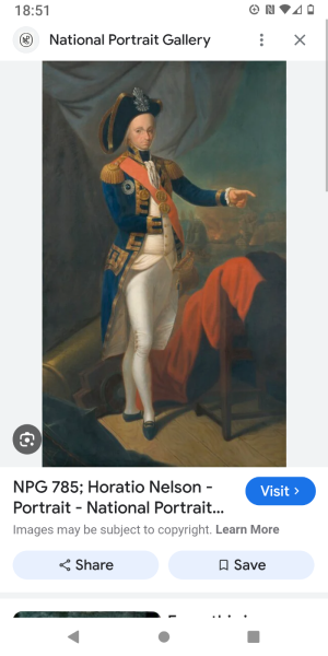
While I am copper-plating the Victory's hull, I decided to print a Horatio Nelson figure in 1:48 scale. I have already printed the same one, only in 1:79 scale for Victory, and I wanted to show how different the scale is. The small figure is 22 mm high, the large one is 40 mm. Nelson was not tall, I even increased it to 175 cm for the tall figure, and left his real height for the smaller figure. I want to conduct the future construction of the ship against the background of the already painted figure in 48th scale to visualize the sizes of the ship's parts against the background of the average person's size. And I have a question, can someone show a color image of the clothes that Nelson is wearing. I want to buy paints, but I don't know how best to paint. Thanks in advance.

Нельсон масштаб.jpg

P.S. the figurine is a scan of the original statue, but I added a headdress for authenticity))
 
Back
Top