- Joined
- Oct 23, 2018
- Messages
- 886
- Points
- 403

 |
As a way to introduce our brass coins to the community, we will raffle off a free coin during the month of August. Follow link ABOVE for instructions for entering. |
 |
 |
The beloved Ships in Scale Magazine is back and charting a new course for 2026! Discover new skills, new techniques, and new inspirations in every issue. NOTE THAT OUR FIRST ISSUE WILL BE JAN/FEB 2026 |
 |

@serikoff Have a view to the position of the joints. The position of the joints depends on the length of the planks.
This is different to your sketch.
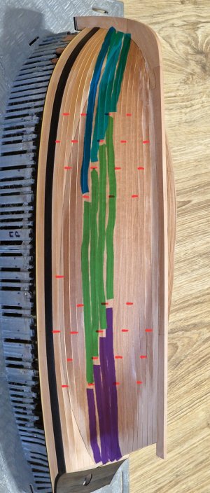
I think it's better to do it as shown in the book. It's both correct and beautiful. As we all know, life isn't always perfect, but you should strive for the best whenever possible. That's my opinion.Fine. I asked because i'm primarily interested in French ships, and i have only a lot of data on them. I don't have anything comparable to British fleet in this period. Any insight is valuable.

I agree, but only partially! On large ships with many joints, this works, but! On small ships, joints shouldn't be in the middle! This makes the ship more fragile. And it's necessary to use the longest possible planks wherever possible. It's impossible to follow all five of these points with a different layout. This has already been tested. If you move the joint further toward the center, you'll end up with four planks instead of three, which contradicts the point about using the longest possible planks and not joining them in the center. That's precisely why I don't have joints in the center and all five points are met. You have the right to do whatever you see fit on your model, but please don't call my design incorrect, as there's no direct evidence to support it, and I've provided my arguments. Thank you very much for the discussion.I know that the example from Goodwin is from a deck. As far as I understood, the English used the same planking scheme also for the hull.
If a plank is ca 28feet long , than you should have a joint every 7 feet (28/4) by the 3 butt shift system. Your scheme shows every joint on less than the half of a plank. This is what I would change.
The simplest method is to use every second double frame for a joint
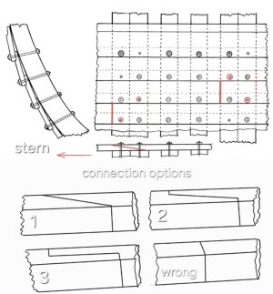

...but since we cannot see these joints, we are only interested in the joint line...
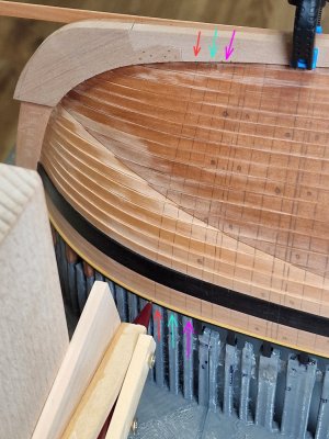
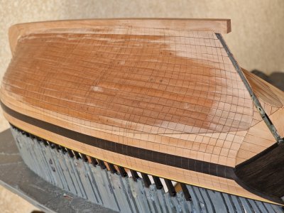
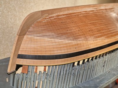
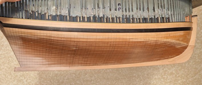


3. Dowels flush with the trim—not authentic, but simpler and less noticeable...
What is cup drill bit?5. I'm considering buying a special cup drill bit that creates a bolt profile, but it's time-consuming (cutting each dowel or piece of wire to the correct profile, or even trying to contour it to the bolt profile on-site).
If only you knew how lazy I am, but the joke hit the mark!You're not going to scarf your joints?
I'm so disappointed.

Your work is beautiful my friend!
 Thanks, friend!
Thank you so much! As I mentioned above, I always try to plan things so that everything is as quick as possible while still looking great and being of excellent quality. Things don't always go according to plan, but that's life.Everyone had different methods of accomplishing the same task. Your results speak volumes for your methods !
Lovely work !!!
I agree, authenticity is all about diagrams, but that's not really my thing. I like a model to have its own signature, and you're right, we often add our own touches, but sometimes it's hard to understand what you want. As for the method with the 0.5 mm protruding dowels, it's actually simple. I'll go into more detail later. After drilling, I'll polish the case and then, without glue, insert a toothpick (birch) into the hole and then nip it off with wire cutters. Then I'll sand down the protruding edge with sandpaper so that only 0.5 mm with a rounded edge is exposed. There's another option, which I'll describe below.I guess you have to come to terms with your definition of "authentic". Authentic would mean sheathing the hull with copper below the waterline and painting with a tar sealant above it. You have already chosen a more stylized approach, so I'm sure whatever you choose will be aesthetically pleasing. Anything you choose that projects from the surface, however will add complication, since you will need to do all of your polishing after drilling the holes, but prior to inserting the "bolts". Given the vast number of bolts, the likelihood to doing it without an errant glue smudge or minor mistake are slim. Then the process of fixing it becomes quite difficult. Perhaps the flush copper, then final polishing, then touch the exposed end with liver of sulfur on a very fine paint brush to blacken it.
Regardless, whatever you choose will no doubt be wonderful.
This burr has already been mentioned on the forum; this is what it looks like. I'm thinking of drilling a small hole in this bowl, and then using it to make the shape I showed in the photo. But that's just a plan; I need to test it out.What is cup drill bit?
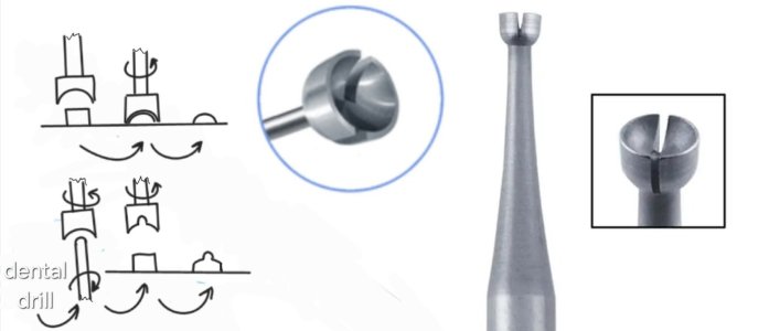
Good morning Sergey. I also want to thank @AnobiumPunctatum and yourself for the robust discussion on planking patterns etc. I am at the stage where I am researching this for my Enterprise and this help a lot. As always Sergey your work is beautiful. Cheers GrantI'd like to thank the @AnobiumPunctatum for bringing the joints to my attention. Although we disagreed on their placement on the hull, and it's not certain I was able to convince him of my design, upon closer examination, I discovered another nuance: my error in the joint itself relative to the frame. As is my habit with conventional planking, I placed the joints (real ones, not imitation) of some planks in the middle of the double frames. And I didn't pay attention to this, even though it was incorrect, and I knew it.
View attachment 549739
The joints on the clinker planks are not edge-on, but rather hooked scarf or plain scarf, as shown in the photo above. This means the visible joint (line on the plank) is not in the middle of the twin frames, but along the end of the twin frame toward the stern, so that the bevel is directed toward the stern, like fish scales.
Now I need to offset the nailing back 4 mm so that the visual joint of the planks is along the aft edge of the twin frames. I have five such joints. Visually, this won't be noticeable, but I might not notice it right away and start placing the joints incorrectly everywhere. Thanks to the @AnobiumPunctatum , I noticed it in time, for which I thank him. Although this question wasn't related to this problem, it helped me indirectly.
As you can see in the photo, the joints could have been 3 or even more options, but since we cannot see these joints, we are only interested in the joint line, and it should run beyond the edge of the double frame towards the stern, and not along the center of the double frames, since the oblique bevel should lie on the frames with its entire surface, and the width of such a bevel is equal to ~8 board thicknesses, which is equal to a double frame - 8 mm.
Thank you. Yes, clinker cladding isn't very common, so there's not much information about it—and most importantly, accurate information. I'm trying to learn and rely on experience. I hope I'm doing it right; in any case, I always consult with the chatGPT.Good morning Sergey. I also want to thank @AnobiumPunctatum and yourself for the robust discussion on planking patterns etc. I am at the stage where I am researching this for my Enterprise and this help a lot. As always Sergey your work is beautiful. Cheers Grant




Ditto....it is really cool how many times Chat GPT refers to SOS.I always consult with the chatGPT
HI Sergey. You have now motivated me to get some glass/plexi for my Xebec and Bounty. Im tired of blowing and dusting the dust off.....I've been busy marking out nailing and joints for the last few days, and also doing a lot of test runs to simulate bolts and nailing. But more on that later, when I have something to show...
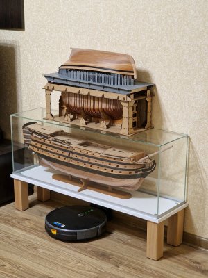
...and today I did something I've been wanting to do for a while:
View attachment 550678
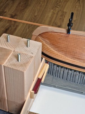
... I added legs to Victoria's "glass coffin."
I described this in detail in the thread at this link:
https://shipsofscale.com/sosforums/...ed-with-john-mckays-anatomy.15458/post-471430
...and now I have a secure place to store all three models. In the future, I think I'll get two more similar coffins for the two Alerts... But they're not ready for that yet..
If you ask the right questions, the chat will respond very well, and you only need to clarify so that it looks for confirmation and never assumes.Ditto....it is really cool how many times Chat GPT refers to SOS.
Yes, dust is a killer for appearance, especially over time. That's why I make a case even during construction, closer to the rigging and after oiling. Good luck.HI Sergey. You have now motivated me to get some glass/plexi for my Xebec and Bounty. Im tired of blowing and dusting the dust off...... Cheers Grant
I'm not sure I understood the question correctly, but I'll say this: any gap in wood or between two parts will be very visible after applying oil. CA glue works similarly. It also greatly highlights cracks by filling them. To prevent it from shining, it needs to be sanded or scraped off, but this will still leave a black line, albeit a matte one. Filling gaps... depends on the purpose. If I want to highlight something with a dark line, I intentionally create such a gap and the glue highlights it, but more often than not, the gap itself under the oil creates the same effect of a dark line. I hope I answered the question, or could you clarify what you mean?Do you know anything about filling gaps in wood with thick CA glue? Have you used this method? I've seen you scrape off CA glue before, but you scrape off excess from gluing.
