• Win a Free Custom Engraved Brass Coin!!!
    As a way to introduce our brass coins to the community, we will raffle off a free coin during the month of August. Follow link ABOVE for instructions for entering.

HMS Alert [1777] 1:48 POF by serikoff. (Two hulls: skeleton and fully rigged)

I'm not sure I understood the question correctly, but I'll say this: any gap in wood or between two parts will be very visible after applying oil. CA glue works similarly. It also greatly highlights cracks by filling them. To prevent it from shining, it needs to be sanded or scraped off, but this will still leave a black line, albeit a matte one. Filling gaps... depends on the purpose. If I want to highlight something with a dark line, I intentionally create such a gap and the glue highlights it, but more often than not, the gap itself under the oil creates the same effect of a dark line. I hope I answered the question, or could you clarify what you mean?
Not all.
I've seen videos where Olha for example, drills holes for dowels, nails, but instead of this nails, she put CA glue into this holes and fills them with CA glue, and next sanded.
Similarly, if there's a large gap in wood, some modelers fills it with glue instead of using putty.
CA fills gaps like putty.
 
To be honest, these three ship models aren't the only ones I have.

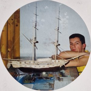
Back in 2002, I started building my first ship, the brig Mercury. I wrote about it earlier in my Victory thread.
It's scary to think, but more than 22 years have passed...

But the main thing is that this photo of me with the ship is the only one I have together. I need to fix that somehow.

20251017_134201.jpg

P1011667.jpg

P1011668.jpg

Naturally, the materials balsa and linden do not correspond to the result one should strive for, therefore this model will remain only in my memory as what it all began with.
 
Chapter 6. Upper Deck
1. Upper Deck (1st hull)

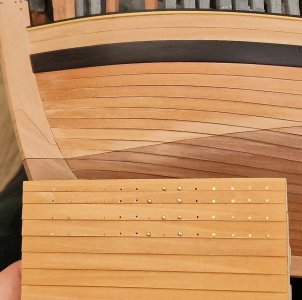
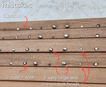
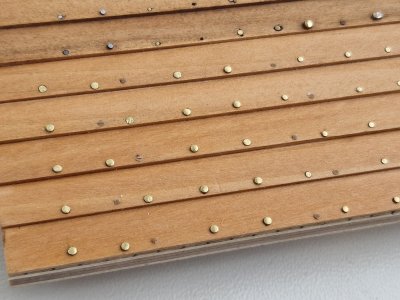
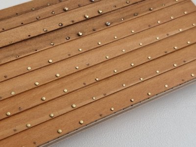
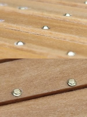
Since I'm currently actively working on the test pieces with imitation bolts and nails (and this takes time), I can't continue with the sheathing yet, so I've returned to the first hull (skeleton) and am continuing to work on the Upper Deck.

Alert 1411.jpg

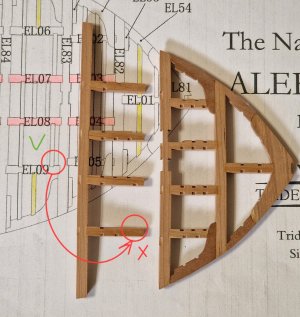
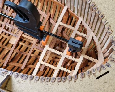
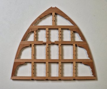
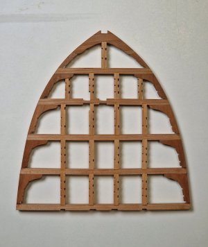
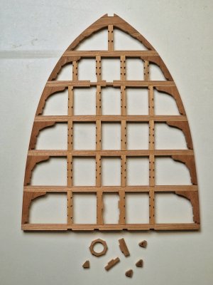
On the right is the finished deck section, on the left are the new parts. And the carlings (parts EL09 and EL06) with missing grooves for the small transverse parts (ledge).

Alert 1412.jpg

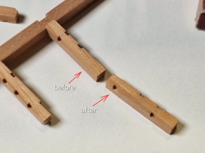
I had to make these grooves as shown in the photo above. Then I glued the third beam.

Alert 1413.jpg

Let me remind you that the deck will be filmed until the very last moment (at least that's what I plan to do, and then we'll see how it turns out).

Alert 1414.jpg

I've written before about how I build a deck, but here's a quick step-by-step description:

Alert 1415.jpg

We have a fore-and-aft section and, say, any beam, and we need to glue four carlings to it.

1. First, I place all four carlings side by side, making sure all the ledge grooves align (otherwise, they will be glued crookedly).

2. I place knees on the sides so that their ledge grooves also align with the carlings.

3. I calibrate one end of all the pieces so that they fit neatly and evenly against the desired beam.

4. I insert the deck section into the hull and place the next beam in its place. I align the carlings with the grooves of the existing beam and determine how much it needs to be shortened relative to the new beam.

5. I calibrate the carlings' length on a grinder and then join everything together without glue and place it in the hull. If everything fits, I glue them together using clamps.

6. Then I remove the deck fragment and...

Alert 1416.jpg

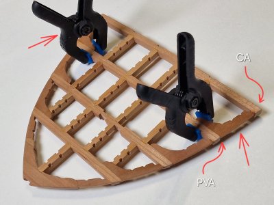
7. ... I glue the knees, the front part with PVA glue, and the small rear part with CA gel. Before that, I sand the parts on all sides and create imitation bolts. By the way, I also sand the carlings on all sides, just like the beams before fitting and gluing them together.

The end result looks like this.

Alert 1417.jpg

If you're having trouble understanding the process from the text description, let me know, and I'll try to take step-by-step photos. I think it'll be clear to anyone who's building this kit, but I'm not sure.

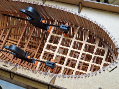
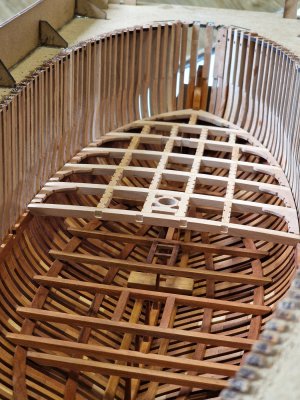
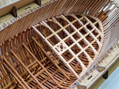
So far, the deck has been easy to remove and reinstall...

Alert 1418.jpg

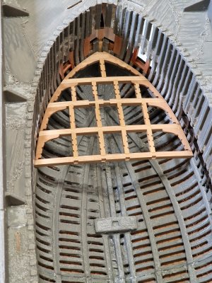
...and most importantly, this deck can easily be installed on a second hull...

Alert 1419.jpg

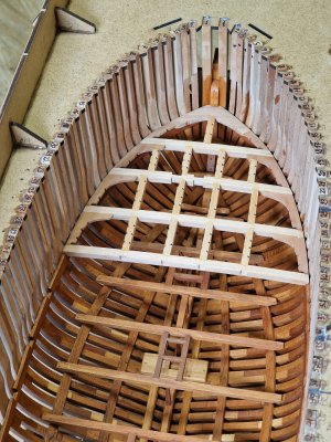
...and we're considering duplicating this deck to quickly and easily create a duplicate for future planking.

So, almost 1/3 of the deck is already complete, but there's still a lot of work to do...
 
Last edited:
Since I'm currently actively working on the test pieces with imitation bolts and nails (and this takes time), I can't continue with the sheathing yet, so I've returned to the first hull (skeleton) and am continuing to work on the Upper Deck.

View attachment 551099

On the right is the finished deck section, on the left are the new parts. And the carlings (parts EL09 and EL06) with missing grooves for the small transverse parts (ledge).

View attachment 551101

I had to make these grooves as shown in the photo above. Then I glued the third beam.

View attachment 551103

Let me remind you that the deck will be filmed until the very last moment (at least that's what I plan to do, and then we'll see how it turns out).

View attachment 551106

I've written before about how I build a deck, but here's a quick step-by-step description:

View attachment 551107

We have a fore-and-aft section and, say, any beam, and we need to glue four carlings to it.

1. First, I place all four carlings side by side, making sure all the ledge grooves align (otherwise, they will be glued crookedly).

2. I place knees on the sides so that their ledge grooves also align with the carlings.

3. I calibrate one end of all the pieces so that they fit neatly and evenly against the desired beam.

4. I insert the deck section into the hull and place the next beam in its place. I align the carlings with the grooves of the existing beam and determine how much it needs to be shortened relative to the new beam.

5. I calibrate the carlings' length on a grinder and then join everything together without glue and place it in the hull. If everything fits, I glue them together using clamps.

6. Then I remove the deck fragment and...

View attachment 551108

7. ... I glue the knees, the front part with PVA glue, and the small rear part with CA gel. Before that, I sand the parts on all sides and create imitation bolts. By the way, I also sand the carlings on all sides, just like the beams before fitting and gluing them together.

The end result looks like this.

View attachment 551109

If you're having trouble understanding the process from the text description, let me know, and I'll try to take step-by-step photos. I think it'll be clear to anyone who's building this kit, but I'm not sure.

So far, the deck has been easy to remove and reinstall...

View attachment 551110

...and most importantly, this deck can easily be installed on a second hull...

View attachment 551111

...and we're considering duplicating this deck to quickly and easily create a duplicate for future planking.

So, almost 1/3 of the deck is already complete, but there's still a lot of work to do...
How do you make such clean and perfect notches in the beams and carlings?
 
How do you make such clean and perfect notches in the beams and carlings?
I don't want to disappoint you, but these are milled parts from a kit. It's a good kit, but still a kit. Yes, like any part, it needs some fine-tuning, but the milling quality is quite good to begin with, so with some skill, you can make a good model from this setup.
At the beginning of this thread, I did a detailed review of this kit:

https://shipsofscale.com/sosforums/...s-skeleton-and-fully-rigged.16066/post-419210
 
I hope you haven't gotten tired of my regular updates... :D

For me, reviewing the project is just as interesting and engaging as the actual construction, so I'll show you a little visual representation of what I tried to explain verbally in the last post.

So, let's go into a little more detail. Any beam-to-beam assembly begins with adjusting one carling beam to length.

Alert 1420.jpg

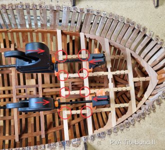
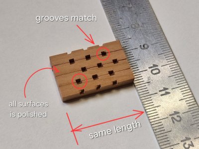
Then I calibrate all 4 to the same size (I make sure that the grooves match, they are circled) and sand all the parts on all sides.

Alert 1421.jpg

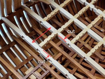
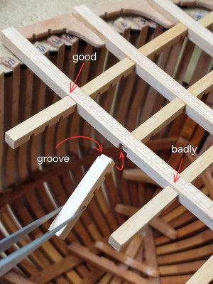
Then I create grooves in the carlings so that they sit completely in the beams and do not stick out above the deck level on top.

Alert 1422.jpg

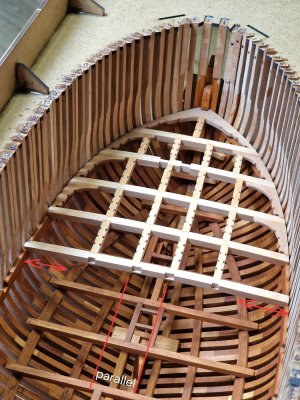
Then I glue everything in place, carefully monitoring the parallelism of the carlings. If necessary, the beam has a small amount of offset, allowing for precise positioning while maintaining parallelism.

Alert 1423.jpg

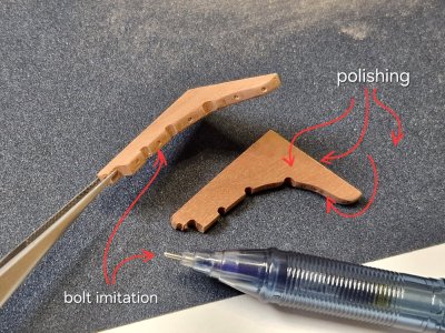
After that, I prepare the Knees: I sand them on all sides and make imitation bolts.

Alert 1424.jpg

Then I pull the deck piece out of the hull and glue the prepared Knees.

Alert 1425.jpg

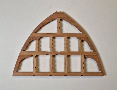
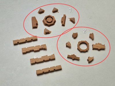
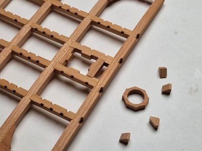
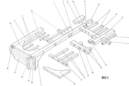
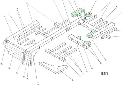
Before this, all the manipulations and details were practically unchanged, but between the next beams there will be a mast insert, and I have two sets of parts for it.

Alert 1426.jpg

I chose the best ones and at first I did everything the same as I showed before...

Alert 1427.jpg

Alert 1428.jpg

... and then glued the first two parts: After and Fore partner chock.

Alert 1429.jpg

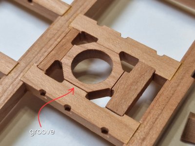
Afterwards, I glued the ring-shaped part, making small gaps between all the parts for better visualization later.

Alert 1430.jpg

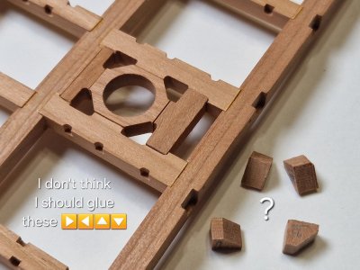
I still haven't found the name of this part, but I'm thinking of not gluing the triangular filling chock pieces on. I like this unfinished look.

Alert 1431.jpg

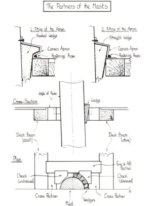
As for the ring-shaped detail, I don't think it ever existed in that form. The mast was secured with spacer wedges driven between the mast and all the other components, filling the entire space that constituted the ring-shaped detail.

Screenshot_20251020_191210_Gallery.jpg

But visually, it looks nice, so I decided to leave it as is.
But maybe I'll change my mind and remove the ring and glue in the triangles... I have spare parts, I can change my mind several times. ROTF

Alert 1432.jpg

Alert 1433.jpg

Alert 1434.jpg

Alert 1435.jpg

Almost half the deck is ready, now it's just Ctrl C - Ctrl V... but if only it were that fast in reality... Cautious:rolleyes:ROTF


Update:

I'm still thinking of removing the ring and gluing in triangles to make it look right. Yes... it looks better with the ring, but it's no longer right. So, I think I'll redo it, especially since it's very simple. According to anatomy.

Screenshot_20251020_193605_Gallery.jpg
 
Last edited:
I hope you haven't gotten tired of my regular updates... :D

For me, reviewing the project is just as interesting and engaging as the actual construction, so I'll show you a little visual representation of what I tried to explain verbally in the last post.

So, let's go into a little more detail. Any beam-to-beam assembly begins with adjusting one carling beam to length.

View attachment 551595

Then I calibrate all 4 to the same size (I make sure that the grooves match, they are circled) and sand all the parts on all sides.

View attachment 551596

Then I create grooves in the carlings so that they sit completely in the beams and do not stick out above the deck level on top.

View attachment 551597

Then I glue everything in place, carefully monitoring the parallelism of the carlings. If necessary, the beam has a small amount of offset, allowing for precise positioning while maintaining parallelism.

View attachment 551598

After that, I prepare the Knees: I sand them on all sides and make imitation bolts.

View attachment 551599

Then I pull the deck piece out of the hull and glue the prepared Knees.

View attachment 551600

Before this, all the manipulations and details were practically unchanged, but between the next beams there will be a mast insert, and I have two sets of parts for it.

View attachment 551601

I chose the best ones and at first I did everything the same as I showed before...

View attachment 551602

View attachment 551603

... and then glued the first two parts: After and Fore partner chock.

View attachment 551604

Afterwards, I glued the ring-shaped part, making small gaps between all the parts for better visualization later.

View attachment 551605

I still haven't found the name of this part, but I'm thinking of not gluing the triangular filling chock pieces on. I like this unfinished look.

View attachment 551606

As for the ring-shaped detail, I don't think it ever existed in that form. The mast was secured with spacer wedges driven between the mast and all the other components, filling the entire space that constituted the ring-shaped detail.

View attachment 551611

But visually, it looks nice, so I decided to leave it as is.

View attachment 551607

View attachment 551608

View attachment 551609

View attachment 551610

Almost half the deck is ready, now it's just Ctrl C - Ctrl V... but if only it were that fast in reality... Cautious:rolleyes:ROTF
A beautiful explanation ! Thank you very much for the detailed explanation! It is very helpful. I did have one question. Like you compared the cut slots on the carlings, does it make sense to mark the center of the beam and compare the slots for the beams where the carlings go? I know there are some places where they were not installed parallel, but most seem to be.

Just a thought. :)
You're right, that's what I do when I check everything, but in the end I still trust my eye, since there can always be a mistake, and you can't fool my eye)))
 
Last edited:
Hey Sergey,

I can't believe you're building such a faulty kit and showing us such a terrible kit!!! Terrible ... :eek: ROTF

No, seriously, where do you get this perseverance and precision from? Your explanations of the individual building steps are also simply marvellous. I always look at and marvel at your ability to work with wood. But I also find your love of putting it in writing incredibly beautiful. It always makes me happy to stop by and take a look at your model. Great and absolute respect. The time you devote to your hobby alone is incredible. Don't stop and keep it up. I'm a big fan of yours.

By the way: Your first picture with your first ship shows how the years go by and how an amateur in modelling has become a true master of his trade ...Exclamation-MarkFirst Place MetalThumbsup
I don't remember if I mentioned it before, but I'd been modeling since 2002, up until 2013. I had a large website and a forum similar to this one. But the war caused a conflict between hosting and image hosting, and after 2022, all the images disappeared from the forum, leaving only text messages. That's when the website and the forum died... as did modeling in Ukraine as a whole. But gradually, I see people slowly getting back together on Facebook, but I haven't seen anything like my website yet. I disappeared for exactly 10 years and didn't touch a ship (Victory), and after the war started (after the borders were completely closed), to keep from going crazy, I returned to the hobby again, as I had a lot of time left over that I used to spend traveling. Now, my hobby is the only thing (besides my family) that brings me pleasure, since everything else is trash in wartime... Thank you for your kind words. We will continue in the same spirit and I will be watching you.

There is so much quality here !!! Thanks for sharing a detailed log as well Sergey. CHeers Grant
Thank you. There's always room for improvement, and we will continue to do so.
 
Hey Sergey,

War is terrible and we can only imagine what it does to you there. It makes me sad and stunned, so much helplessness. I'm glad you've found something to take your mind off it. It's not just your family, but also your hobby that makes you stronger! Thank you for being with us ... :D Thumbsup
 
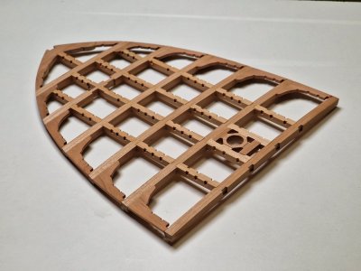
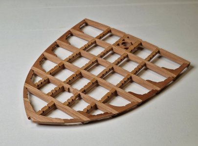
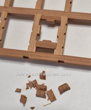
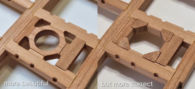
Still couldn't resist and got to work, just now, I redid the partners' masts. :eek:ROTF
Yes, I liked the original look better, but it needs to be done according to the canon, because...

Alert 1436.jpg

... I removed a non-existent part (which the kit manufacturer invented and which simply doesn't exist—I'm talking about the ring-shaped part).

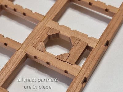
I installed the triangular partners, and now all the parts are in place and...

Alert 1437.jpg

... the most important thing is that everything is correct now. ;)

Alert 1438.jpg

The exterior is still natural—not final. Everything will still be sanded and polished flush with the deck, but I'll leave small gaps between elements to better visualize individual details.

P.S. although, I already like it. :rolleyes:
P.P.S. thanks, Gunther (@GIG1810), for the kind words.
 
Well explained and photographed. You have the makings of a nice "how to" book. It has been a good fifteen years or so since the last ones came out and with all the new technology as well as accessibility to archival information available, the timing might be right.
Allan
 
Still couldn't resist and got to work, just now, I redid the partners' masts. :eek:ROTF
Yes, I liked the original look better, but it needs to be done according to the canon, because...

View attachment 551969

... I removed a non-existent part (which the kit manufacturer invented and which simply doesn't exist—I'm talking about the ring-shaped part).

I installed the triangular partners, and now all the parts are in place and...

View attachment 551970

... the most important thing is that everything is correct now. ;)

View attachment 551971

The exterior is still natural—not final. Everything will still be sanded and polished flush with the deck, but I'll leave small gaps between elements to better visualize individual details.

P.S. although, I already like it. :rolleyes:
P.P.S. thanks, Gunther (@GIG1810), for the kind words.
That is looking much better, Sergey. With some nice compassion pictures.
Regards, Peter
 
Well explained and photographed. You have the makings of a nice "how to" book. It has been a good fifteen years or so since the last ones came out and with all the new technology as well as accessibility to archival information available, the timing might be right.
Allan
I was thinking about this even before the hiatus, before 2014, but now there's so much information online and great reviews that I can't really say anything new. I'm trying to help those interested by using what I do as an example. But I think if we could go back 20-25 years, it would be relevant. ;)

That is looking much better, Sergey. With some nice compassion pictures.
Regards, Peter
I feel the same way every time I watch it. But in this case, you have to try to make it look like it was on a real ship, whenever possible. :cool:
 
As always, beautiful work and wonderful explanations using text and pictures !!!
I consider myself a mediocre modeler that still has a lot to learn and your information is wonderful and helpful !
Thank you !
Thank you very much. I always compare it to learning to play a musical instrument. You need basic knowledge and definitely practice. Sometimes people have talent, but persistence is much more important, because practice makes perfect. Good luck, I'm sure you'll succeed.
 
Back
Top