HMS Alert by DST

Thanks everybody

...I like it more, when the kit designer is making the beams on both sides maybe 1mm longer, (with the info in the manual that the modeler has to make the length adjustments equal on both sides....
I agree, that would make fitting thise pieces way easier.

...I suppose you could scab on a little piece of wood on the ends of the beam...
I think that will be a good solution, even when it will be hidden by the waterway. But for stability alone it will be worth.

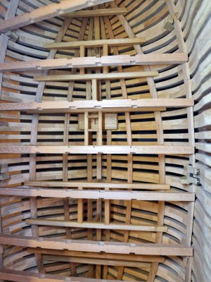
So after fixing the foremost parts of the deck clamps and temporarily fixing the aft parts I could check the length of all the beams. Only amidships the beams are too short, so maybe I sanded too much that area... but 1mm on either side?! I'm not sure....

20240821_204519.jpg

20240821_204531.jpg

Shaping the first beam. It is laborious to adapt it to the geometry of the frames but worth the effort. A tight fit always gives a sense of satisfaction and keeps You motivated to continue working.
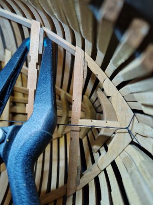
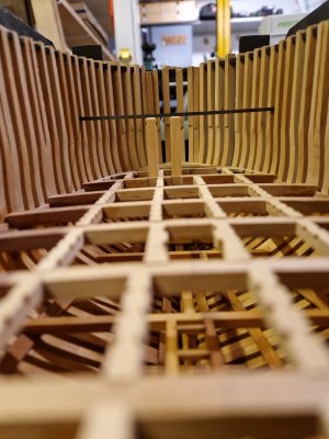
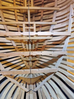
I stole, or maybe borrowed, dockattners system to establish the centerline and thus keeping the beams centered across the length of the ship. Works really good:

20240821_210512.jpg

20240821_211645.jpg

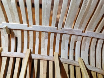
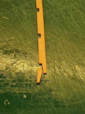
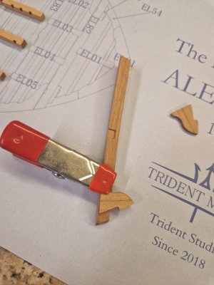
While trying to adapt the middle section of the deck clamp the scarph joint broke off, of course. I had to reglue it several times, finally using CA glue and glued it in place.

20240826_201739.jpg

The joint is not great and I tried to hide it with PVA and wood dust from sanding:

20240827_080606.jpg

This is how it turned out:

20240827_081029.jpg

Should be OK once the deck is installed I doubt it will be visible.

That's it for now, thank You for visiting
 
You could say that You learn from Your mistakes but ...apparently not.
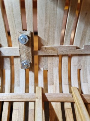
I did follow the exact same procedure to shorten the second deck clamp as the one that broke before and behold:

20240829_172107.jpg

Who would have thought, it broke the exact same way as before.

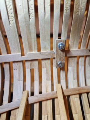
The aft joint is quite good:

20240829_184242.jpg

And this is the one that broke, shortened and repaired... better than the other side

20240829_184250.jpg

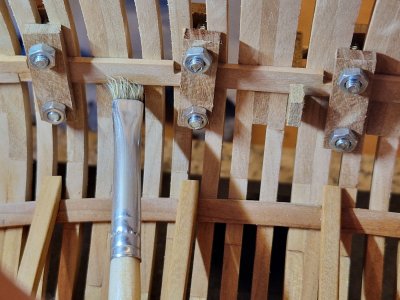
Cleaning glue squeezeout with a dampened brush...

20240829_184551.jpg

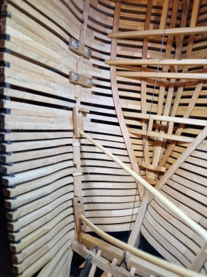
"Clamping" the aft piece of the deck clamp with different methods like rubberbands and bamboo skewers because my screw clamps do not fit between the frames...

20240829_192146.jpg

20240830_071155.jpg

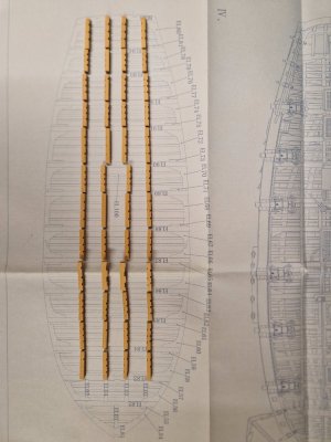
Here are the deck beams. I tried to lengthen them by glueing pieces of cherry veneer on the ends. Still not sure about why they are too short. Did anyone have the same issue with his build?

20240829_185401.jpg

Thank You
 
Last edited:
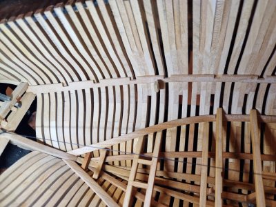
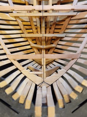
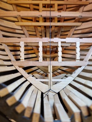
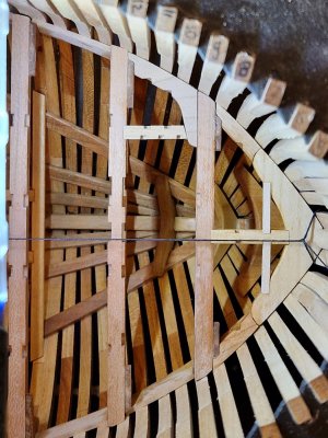
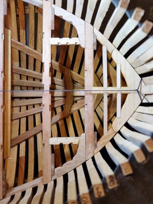
After adding material to both ends of the beams I checked the alignment with the help of the notches for the carlings. Not perfect but better...

20240904_193512.jpg

Installing the breasthook. This was straightforward sand/testfit/repeat procedure.

20240908_210120.jpg

20240908_210132.jpg

Since everything depends on everything else I will not glue anything in place yet. The first
carling is adapted to the beam.

20240908_215411.jpg

And the first ledge is in place. I just have to repeat that about a hundred times to complete the deck...

20240908_220454.jpg
 
It Looks very very nice. I learnt by myself beams are always too scarce once adjustet and polished. And sometimes even before that... . Cheers!
 
I'm confident the care you are taking will result in a fine outcome!

I was finally able to remove my alignment string this past week. That was a happy moment! In case you haven't noticed yet, that thing is ALWAYS in the way ROTF.
 
better alignement is already much better than before -
you will see the result (and be happy that you did the preparation) when all carlings etc. are installed
 
Small steps and little time, so progress is really slow.
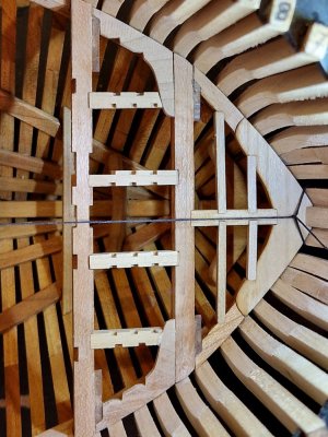
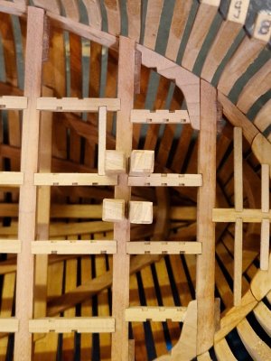
The next 4 carlings are fitted to the next beam:

20240909_202321.jpg

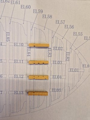
And on the next ones I encountered a "problem". I located parts 6, 7, 8 and 9 from billet no. 15 and the first thing I noticed is the numbering on the carlings is wrong and on 2 of them notches are missing.
Or I just do not understand the plans... .
So from top down it should be number 6 (I am not a number! I am a free man!! ROTF couldn't resist that one) to number 9.
6 and 9 are missing a notch for the foremost ledges. On carling 8 the is one but not on 9...

As I understand between 6 and 7 isn't a fore ledge to leave room for the bitts of the windlass. That's why there is a bigger cutout in carling 7.
But on the starboard side could very well be one since there's nothing in the way... I could add the notch that's easy but I want to be sure that this is correct.

I guess I have to check on the other builds again and test with the parts from the bitts...

20240921_173638.jpg
 
I just read the whole of this thread. It’s a drama and a masterclass. Thank you for being so open and honest about all the difficulties which you have overcome, that gives me heart to build POF for myself. Without the knowledge that builder and manufacturer errors can be fixed, I would find the complexity of the build method too scary to attempt and be forever limited to POB.
 
I just read the whole of this thread. It’s a drama and a masterclass. Thank you for being so open and honest about all the difficulties which you have overcome, that gives me heart to build POF for myself. Without the knowledge that builder and manufacturer errors can be fixed, I would find the complexity of the build method too scary to attempt and be forever limited to POB.
Similar I was thinking in the past
but after the first POF - you get the feeling, that you never want to a POB once more
To build a ships structure with frames, beams, carlings etc. is highly interesting and also the additional research (if necessary)
Try it
 
To build a ships structure with frames, beams, carlings etc. is highly interesting and also the additional research (if necessary)
Try it

I shall. I have two PoF kits in the stash already; Emma C Berry by Model Expo and Le Requin by ZHL. I want to build Charles W Morgan (Model Expo) first for the experience of the complex rigging, and of course there's my Alert to complete. Its all part of 'Smithy's Five Year Plan' :)
 
Thank You. Indeed it is a drama, especially the start where I was a bit disappointed with what would be small and correctable flaws.
My overall mood was quite bad at that time...

Anyway, I didn't have much time left to build.
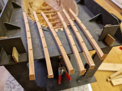
I prepared all the carlings and verified them on the plan. There are quite a few that have inverted part numbers...

20241015_183528.jpg

20241016_185948.jpg

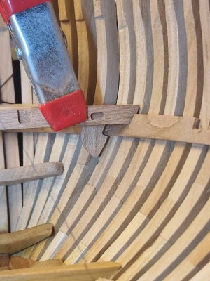
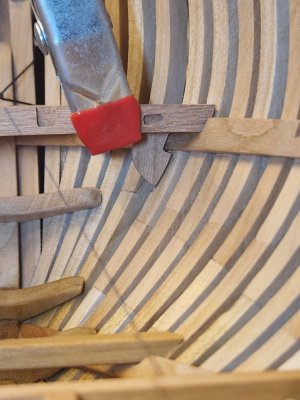
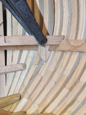
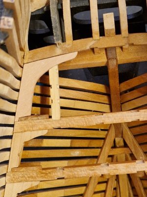
I will install the hanging knees first. Testing the fit of the part before sanding to the final shape:

20241017_174110.jpg

20241017_173741.jpg

Starting to file and sand the angke between the beam and the bow curve:

20241017_174451.jpg

And testing the fit again...

20241017_174715.jpg

And after several repetitions of these steps it looks like this:

20241017_181315.jpg

The knee still needs to come up a little:

20241017_181426.jpg

The second knee went a lot faster. I had to cut a small notch for the part EL 54 to avoid thinning that piece too much...

20241017_183324.jpg

So I just have to repeat that like 100 times and then on to the carlings
 
A small update on the beams and hanging knees.

20241019_185901.jpg

Every beam has to be surface finished on the underside before installation as it is difficult to do so afterwards. The bow section was glued up and I had to cut a brush to be able to apply the oil.

Thus is the actual stage:

20241022_072345.jpg

20241022_072353.jpg
 
Your work is exemplary! One thing that I found can cause problems later on (at least for me) with the elevation of the guns in the ports is if the beams are the proper thickness and then are let down into the clamps too far or not far enough. FWIW, at times they were let down but not always. If the clamps were scored for the beams, it would only be an inch (Goodwin, The Construction and Fitting of the English Man of War, page 66.) I found that testing with a beam under a port with a piece of wood on top to represent the thickness of the deck planking and setting one finished gun & carriage on this test set up will show if the beams need to be let down into the clamp and how much.
Allan
 
Last edited:
Looks great!. This is very tedious work with the knees... but it is part and parcel of the POF model so convince yourself that you're having fun :).
Oh I'm having fun. I'm advancing at a good pace.

Your work is exemplary! One thing that I found can cause problems later on (at least for me) with the elevation of the guns in the ports is if the beams are the proper thickness and then are let down into the clamps too far or not far enough. FWIW, at times they were let down but not always. If the clamps were scored for the beams, it would only be an inch (Goodwin, The Construction and Fitting of the English Man of War, page 66.) I found that testing with a beam under a port with a piece of wood on top to represent the thickness of the deck planking and setting one finished gun & carriage on this test set up will show if the beams need to be let down into the clamp and how much.
Allan

Thank You for that tip, I will definitely consider it. All the beams and knees are installed by now, so I'm afraid it will be too late to correct anyways...


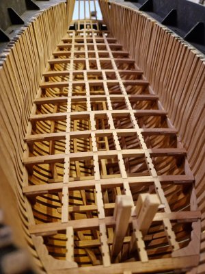
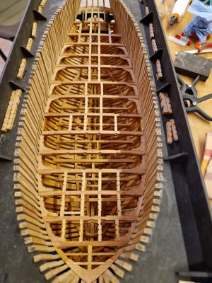
So the progress so far:

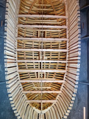
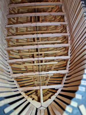
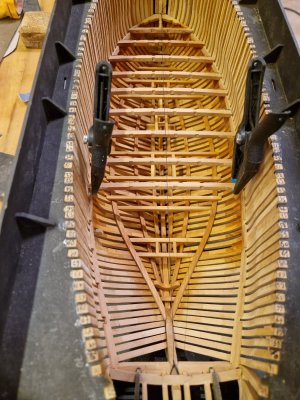
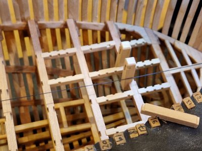
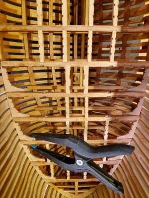
All the beams and knees are installed and I started fitting carlings in the bow

20241023_143705.jpg

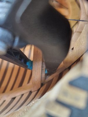
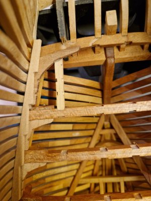
So this is the first one where a lodging knee has to be fitted. Worked well so far...

20241025_143056.jpg

On the starboard side I cut a little too much so I repaired that with a small piece of cherry veneer... once it is sanded it should be fine.

20241025_145939.jpg

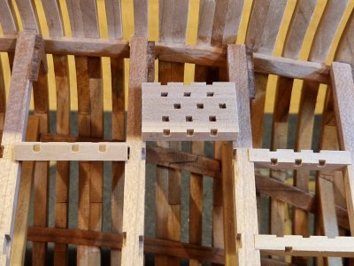
And here is the first set of four

20241028_145250.jpg

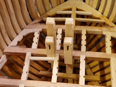
Testfitting alignment of the jibboom bitts

20241028_155049.jpg

I found it way easier to cut out a small amount on the underside of the carlings than to try to square of the notches in the deck beams...

20241028_163236.jpg

When I installed the deck clamp I had to cut about 1,5mm to make it fit. These 1,5mm are now showing up in the carlings between beam 3 and 4 being too long.
I had to sand these 4 parts down to make them fit. The carlings for the next beams are about 1mm too short so I have to adjust these with veneer too Cautious

20241028_164243.jpg

Let's hope this does not cause trouble further in the build...

Speaking of trouble. I realized that beam number 5 was glued in the wrong way.
The wider notches should face aft...

20241028_164901.jpg

... so I had to remove them. This time I only applied heat with the heatgun and they came loose in about a matter of 2 minutes.
And surprisingly clean:

20241028_165419.jpg

Also no mess on the deck clamp. That was easy

20241028_165425.jpg

So now on to repairing the error...
Thank You for Your interest
 
The beam has been positioned in the right direction

20241028_193326.jpg

Some carlings are a bit off but I think I should be able to correct this

20241028_201111.jpg

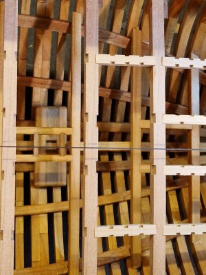
The rest has been adjusted in the length and positioned in place

20241029_130811.jpg

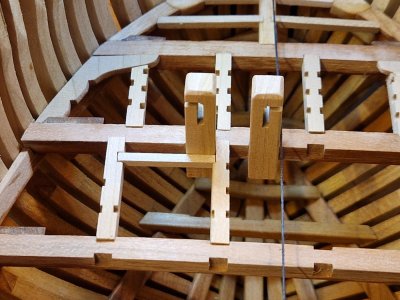
Testing the fit of the mast bitts

20241029_141016.jpg

Everything sits snugly into place. This should make it easy for later installation

20241029_141435.jpg

Not too bad, a little adjusting and it should turn out OK

20241029_141505.jpg

20241029_141450.jpg
 
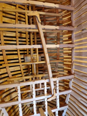
Started installing lodging knees.
Can't wait to finally cut the hull from the building berth.

I thought about making a stand to be able to present it as is while continuing building her.
And that's where I realised I forgot to insert nuts in the keel Cautious as I intended to mount the ship on pedestals made from brass.
I guess I have to find another solution then.

20241029_182847.jpg

20241106_171053.jpg
 
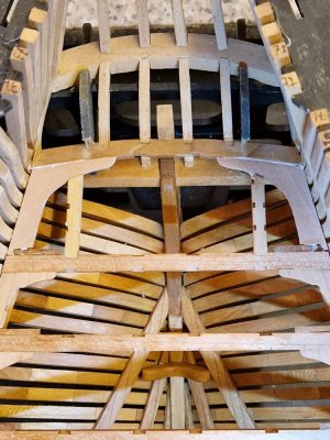
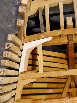
While testfitting the aftmost knee I realised that it was too short. Or maybe I did something wrong on the stern assembly...

I thought I could hide that gap under the waterway but it will be visible (see the gap near the hanging knee)

20241111_182625.jpg

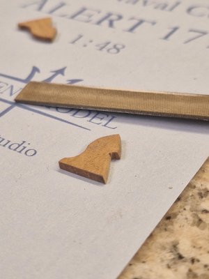
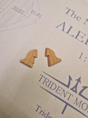
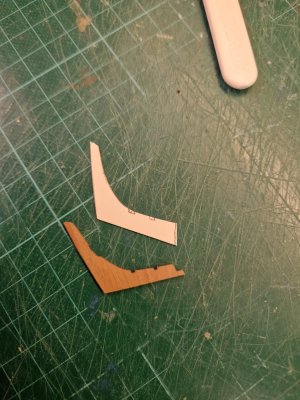
So I had to make a new one. There was no more cherry left big enough for a knee or two for that matter so I had to cut it from a piece of pear. This is the closest wood I could find in terms of color matching. Once it's oiled it should match the color of the cherry enough to blend in with the rest of the model

This is the paper template

20241111_183229.jpg

The part cut out and a first testfit

20241113_175259.jpg

After several sanding and fitting it looks good

20241113_180253.jpg

This completes all the lodging knees and on to glueing the ledges in place. Should be straightforward...

Thank You for Your interest

20241113_184612.jpg
 
Back
Top