Thx gents for all your comments.
-

Win a Free Custom Engraved Brass Coin!!!
As a way to introduce our brass coins to the community, we will raffle off a free coin during the month of August. Follow link ABOVE for instructions for entering.
-

PRE-ORDER SHIPS IN SCALE TODAY!
The beloved Ships in Scale Magazine is back and charting a new course for 2026!
Discover new skills, new techniques, and new inspirations in every issue.
NOTE THAT OUR FIRST ISSUE WILL BE JAN/FEB 2026
- Home
- Forums
- Ships of Scale Group Builds and Projects
- HMS Alert 1777 1:48 PoF Group Build
- HMS Alert 1777 1:48 Group Build Logs
You are using an out of date browser. It may not display this or other websites correctly.
You should upgrade or use an alternative browser.
You should upgrade or use an alternative browser.
Following Jim on his fantastic build of his gun carriages I also build one for my copper plated test gun barrel.
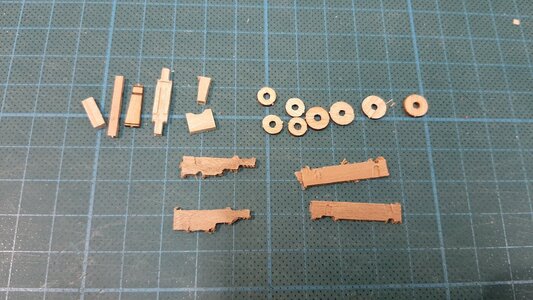
First collected all the wood parts. I am going to use all kit parts.
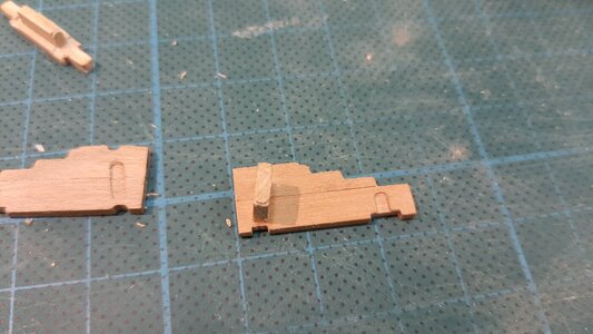
To fit the parts properly in the milled slots I have to adapt the edges with a rounded shape.
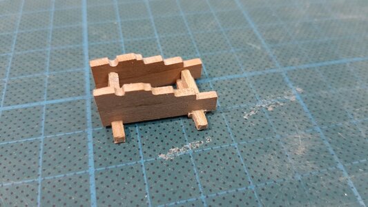
All frame parts glued with CA.
The remaining parts and the wheels. The wheels I sand and shape using my proxxon drill.
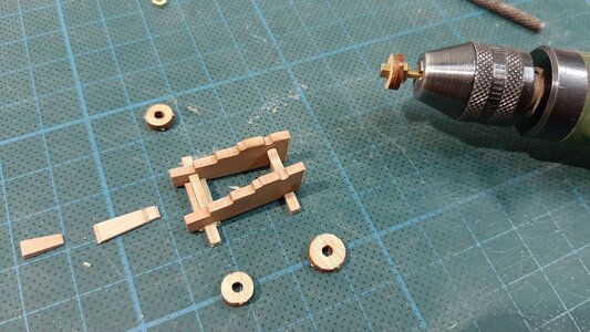
In the outer surface of the wheel I turned a recess for fitting the wheel bolts.
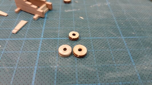
After rounding the axles I dry fitted the wheels, here you can clearly see the recess area in the wheels.
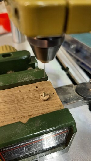
For drilling the bolt holes I made a template to get the holes at the same distance from the center for every wheel.
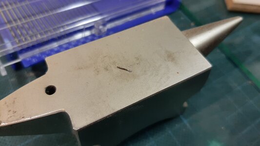
Hammering a locking pin for the wheel axle.
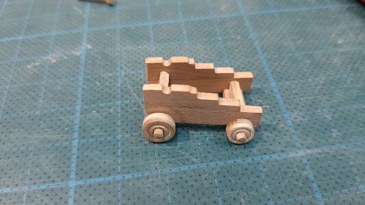
Dry fitting the wheels and locking pins.
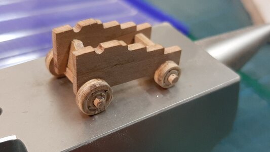
Painting it with vermillion red ink, a UV resistant water based pigmented ink from Schminke which is new and a test.
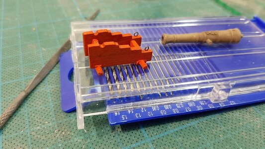
Preparing eye bolts from 0,3 mm annealed steel wire. Compared to the kit provided copper eyebolts.
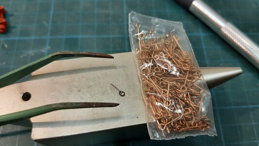
Eye bolts fitted.
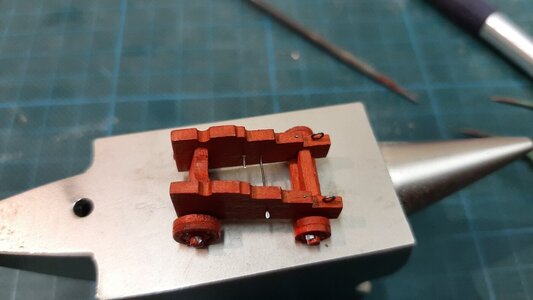
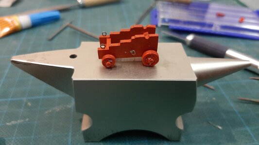
Dry fitting my copper plated gun barrel.
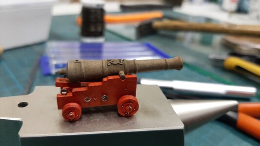
Next are fitting some details like the barrel adjustment block which I fitted with a rope loop. The hoops around the axle end which I made from heat shrink. The gun barrel slots.
All ready for action.
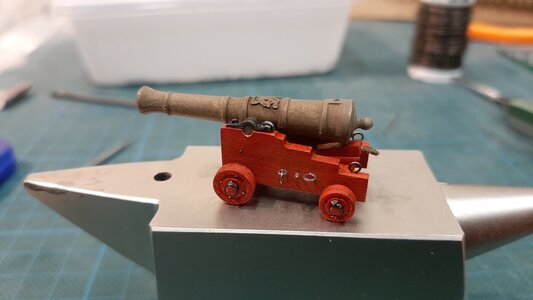
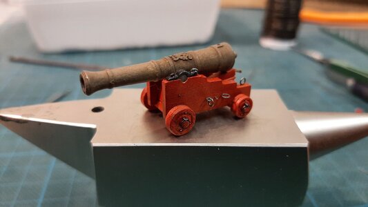
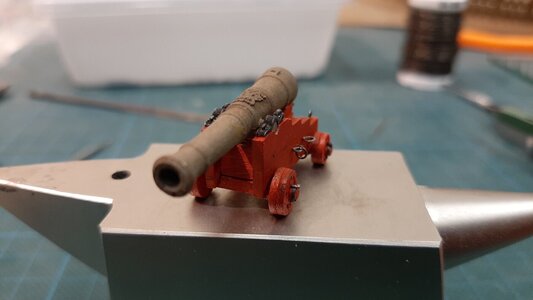
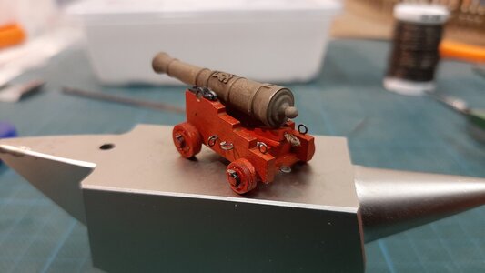
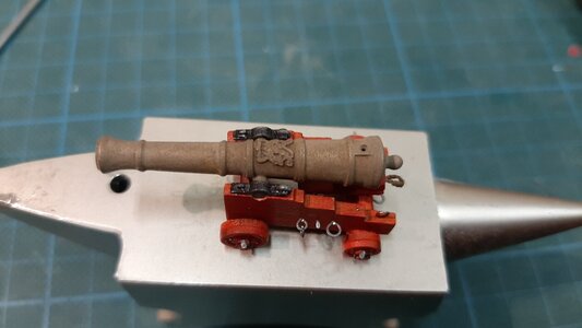
You see all these models are build from the same kit but will be different from each other just by your own input, everything is possible.
First collected all the wood parts. I am going to use all kit parts.

To fit the parts properly in the milled slots I have to adapt the edges with a rounded shape.

All frame parts glued with CA.

The remaining parts and the wheels. The wheels I sand and shape using my proxxon drill.

In the outer surface of the wheel I turned a recess for fitting the wheel bolts.

After rounding the axles I dry fitted the wheels, here you can clearly see the recess area in the wheels.

For drilling the bolt holes I made a template to get the holes at the same distance from the center for every wheel.

Hammering a locking pin for the wheel axle.

Dry fitting the wheels and locking pins.

Painting it with vermillion red ink, a UV resistant water based pigmented ink from Schminke which is new and a test.

Preparing eye bolts from 0,3 mm annealed steel wire. Compared to the kit provided copper eyebolts.

Eye bolts fitted.


Dry fitting my copper plated gun barrel.

Next are fitting some details like the barrel adjustment block which I fitted with a rope loop. The hoops around the axle end which I made from heat shrink. The gun barrel slots.
All ready for action.


You see all these models are build from the same kit but will be different from each other just by your own input, everything is possible.
And all are nicely done. RichFollowing Jim on his fantastic build of his gun carriages I also build one for my copper plated test gun barrel.
First collected all the wood parts. I am going to use all kit parts.
View attachment 224536
To fit the parts properly in the milled slots I have to adapt the edges with a rounded shape.
View attachment 224537
All frame parts glued with CA.
View attachment 224538
The remaining parts and the wheels. The wheels I sand and shape using my proxxon drill.
View attachment 224539
In the outer surface of the wheel I turned a recess for fitting the wheel bolts.
View attachment 224540
After rounding the axles I dry fitted the wheels, here you can clearly see the recess area in the wheels.
View attachment 224541
For drilling the bolt holes I made a template to get the holes at the same distance from the center for every wheel.
View attachment 224543
Hammering a locking pin for the wheel axle.
View attachment 224544
Dry fitting the wheels and locking pins.
View attachment 224545
Painting it with vermillion red ink, a UV resistant water based pigmented ink from Schminke which is new and a test.
View attachment 224546
Preparing eye bolts from 0,3 mm annealed steel wire. Compared to the kit provided copper eyebolts.
View attachment 224547
Eye bolts fitted.
View attachment 224548
View attachment 224549
Dry fitting my copper plated gun barrel.
View attachment 224550
Next are fitting some details like the barrel adjustment block which I fitted with a rope loop. The hoops around the axle end which I made from heat shrink. The gun barrel slots.
All ready for action.
View attachment 224553
View attachment 224554
View attachment 224555
View attachment 224556
View attachment 224557
You see all these models are build from the same kit but will be different from each other just by your own input, everything is possible.
Fantastic canons and great presentation, my friend! One thing I want to add is all the parts are supplied in the kit, and the cannons looking great out of the box!You see all these models are build from the same kit but will be different from each other just by your own input, everything is possible.
Thx gents for comments and likes.
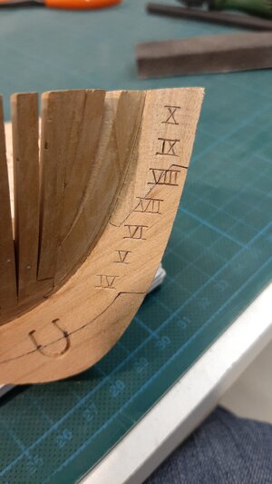
The next step is adding the depth markings in the stem and stern. In the stem these are carved on the SB side, on the stern on the PS side.
The markers used are feet carved in roman numerals.
At 1:48 scale every foot is 0,635 mm.
First I measured from the bottom of the stem towards the top and set horizontal lines.
The lower line of the roman numeral is the depth marker, the number is carved above it.
The space between the numerals is the same as the height of the numeral. Between the markers I drew additional lines and between these I drew the numerals. Keep in mind these numerals are perpendicular to the waterline and not the keel. This means they are on a slight angle.
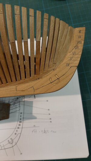
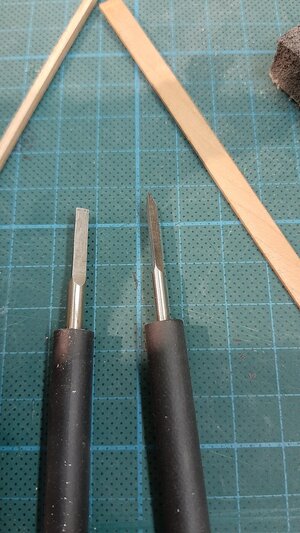
Then with my alibaba micro chisels I carved out the numerals.
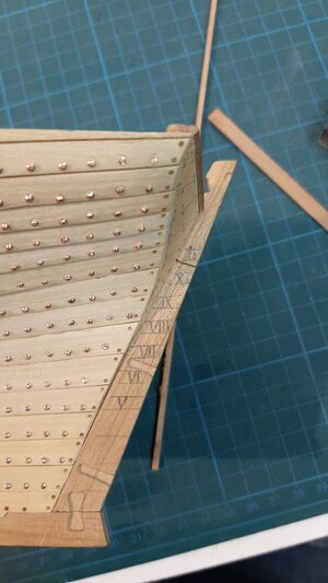
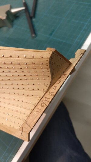
The same process to be repeated on the PS side of the stern.
The next step is adding the depth markings in the stem and stern. In the stem these are carved on the SB side, on the stern on the PS side.
The markers used are feet carved in roman numerals.
At 1:48 scale every foot is 0,635 mm.
First I measured from the bottom of the stem towards the top and set horizontal lines.
The lower line of the roman numeral is the depth marker, the number is carved above it.
The space between the numerals is the same as the height of the numeral. Between the markers I drew additional lines and between these I drew the numerals. Keep in mind these numerals are perpendicular to the waterline and not the keel. This means they are on a slight angle.

Then with my alibaba micro chisels I carved out the numerals.


The same process to be repeated on the PS side of the stern.


Very nicely done handwork. RIchThx gents for comments and likes.
The next step is adding the depth markings in the stem and stern. In the stem these are carved on the SB side, on the stern on the PS side.
The markers used are feet carved in roman numerals.
At 1:48 scale every foot is 0,635 mm.
First I measured from the bottom of the stem towards the top and set horizontal lines.
The lower line of the roman numeral is the depth marker, the number is carved above it.
The space between the numerals is the same as the height of the numeral. Between the markers I drew additional lines and between these I drew the numerals. Keep in mind these numerals are perpendicular to the waterline and not the keel. This means they are on a slight angle.
View attachment 224691
Then with my alibaba micro chisels I carved out the numerals.
View attachment 224692
View attachment 224693
The same process to be repeated on the PS side of the stern.
View attachment 224695
View attachment 224696
Questa è solo una grande esecuzione, amico mio! Sei un tuttofare e un maestro d'ascia in un unico pacchetto.The next step is adding the depth markings in the stem and stern. In the stem these are carved on the SB side, on the stern on the PS side.
The markers used are feet carved in roman numerals.
At 1:48 scale every foot is 0,635 mm.
First I measured from the bottom of the stem towards the top and set horizontal lines.
The lower line of the roman numeral is the depth marker, the number is carved above it.
The space between the numerals is the same as the height of the numeral. Between the markers I drew additional lines and between these I drew the numerals. Keep in mind these numerals are perpendicular to the waterline and not the keel. This means they are on a slight angle.
I wonder when load markings first appear and where? Shallow harbors and crossings would necessitate such devices in addition to sounding lead lines. RichQuesta è solo una grande esecuzione, amico mio! Sei un tuttofare e un maestro d'ascia in un unico pacchetto.
Here you go, RichI wonder when load markings first appear and where? Shallow harbors and crossings would necessitate such devices in addition to sounding lead lines. Rich

Waterline - Wikipedia
Thanks for the link with the historical background. Wiki is always there but sometimes questions come ahead of my own searching. Rich
We have to be a little bit more precise......
The markings Maarten made are the so called AHMINGS (in german also Tiefgangsmarken) means the water gauge, draft or draught marks, which are measured from the bottom of the keel - mainly they were used also to measure the trim of the ship during the loading - they were helping to define the total number of ballast and the correct locations of the ballast and storage...... These data from the bow and stern, the captains had toi write down in their log-books, before they leave the harbour....... so it was inportant to know and to check....
The waterline or Plimsoll-Marking is slightly different and were introduced as hull markings much later. Ahmings were already used in the middle age

 en.wikipedia.org
 de.wikipedia.org
The markings Maarten made are the so called AHMINGS (in german also Tiefgangsmarken) means the water gauge, draft or draught marks, which are measured from the bottom of the keel - mainly they were used also to measure the trim of the ship during the loading - they were helping to define the total number of ballast and the correct locations of the ballast and storage...... These data from the bow and stern, the captains had toi write down in their log-books, before they leave the harbour....... so it was inportant to know and to check....
The waterline or Plimsoll-Marking is slightly different and were introduced as hull markings much later. Ahmings were already used in the middle age

Draft (hull) - Wikipedia
Schiffsmaße – Wikipedia
SoS exchanges offer a great way of expanding the brain bucket. Thanks, RichWe have to be a little bit more precise......
The markings Maarten made are the so called AHMINGS (in german also Tiefgangsmarken) means the water gauge, draft or draught marks, which are measured from the bottom of the keel - mainly they were used also to measure the trim of the ship during the loading - they were helping to define the total number of ballast and the correct locations of the ballast and storage...... These data from the bow and stern, the captains had toi write down in their log-books, before they leave the harbour....... so it was inportant to know and to check....
The waterline or Plimsoll-Marking is slightly different and were introduced as hull markings much later. Ahmings were already used in the middle age

Draft (hull) - Wikipedia
en.wikipedia.org
Schiffsmaße – Wikipedia
de.wikipedia.org
Next to working on our kitchen extension with large oak beams I still found some time to work on the little Alert.
This time the pump well and shot locker.
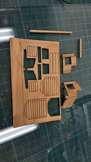
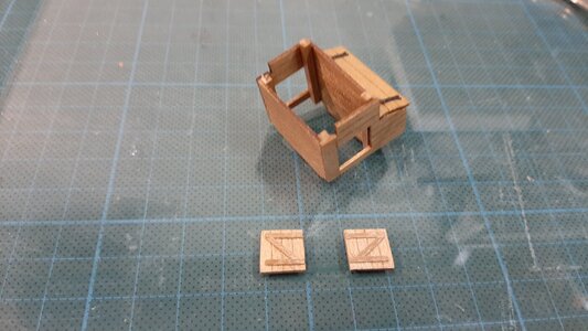
All the wood parts together.
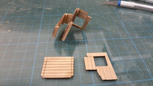
The first setup, all glued with CA.
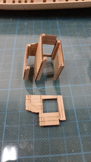
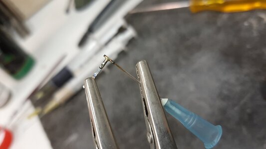
For the hinges I dont use kit parts but make these from anealed wire and 0,6 mm seringe needles.
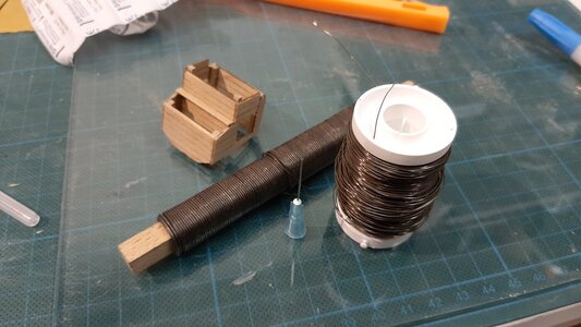
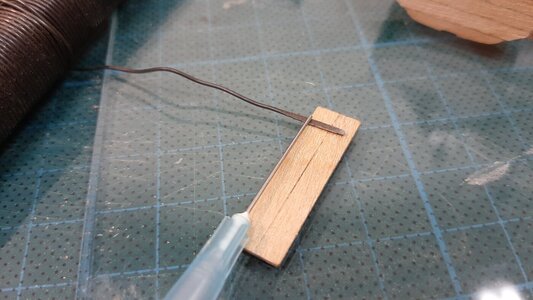
The needle is silver soldered to the hinge
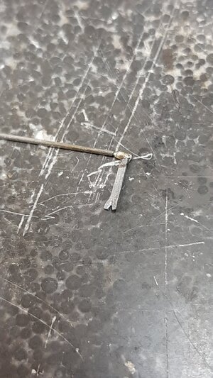
0,4 mm wire fits in the 0,6 mm needle to create a perfect fit for the hinges.
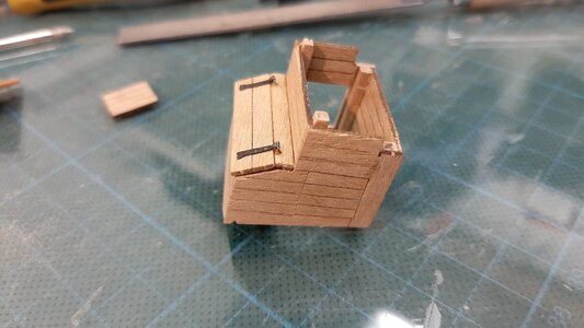
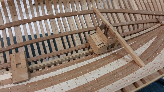
Dry fitting it under the temporary fitted deck beam.
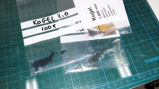
The shot locker I fill with 6 pounder cannon balls, 2 mm to scale. Burnished black ball bearings.
Applied with a layer of shellack.
Next will be the doors.
The reinforcements on the inside as discussed in jim s perfect blog.
Fitting the hinges and door handles.
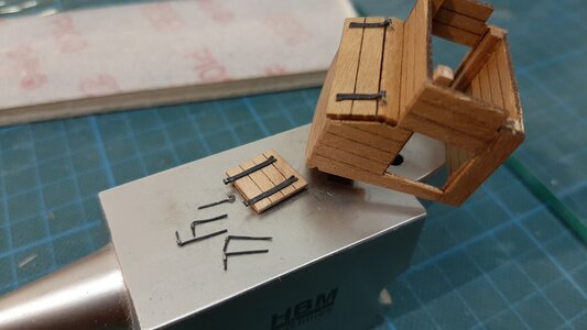
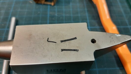
These simple doors I lock with a simple clamp.
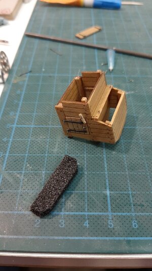
Time to fill the shot locker. I first put some clear glue on a pieces of foam. The foam I push from tge bottom in the shot locker.
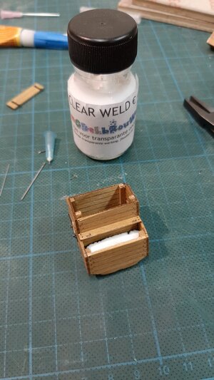
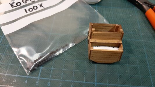
Cannon balls on top
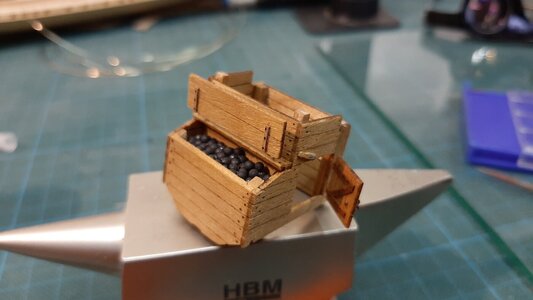
And the finished product.
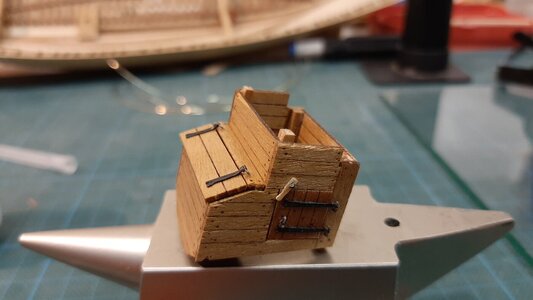
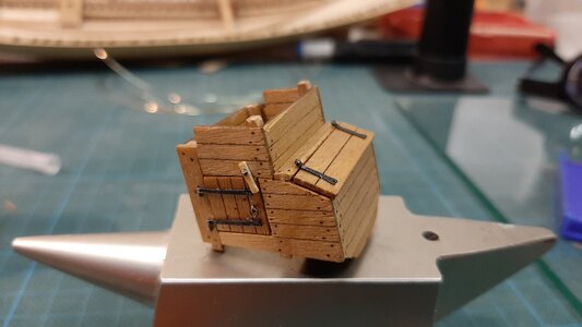
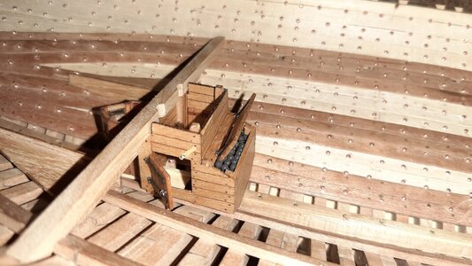
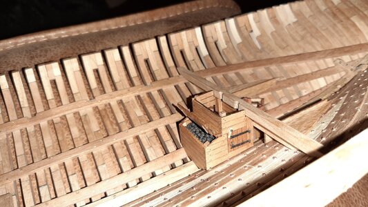
This time the pump well and shot locker.
All the wood parts together.

The first setup, all glued with CA.


For the hinges I dont use kit parts but make these from anealed wire and 0,6 mm seringe needles.


The needle is silver soldered to the hinge

0,4 mm wire fits in the 0,6 mm needle to create a perfect fit for the hinges.

Dry fitting it under the temporary fitted deck beam.

The shot locker I fill with 6 pounder cannon balls, 2 mm to scale. Burnished black ball bearings.

Applied with a layer of shellack.
Next will be the doors.
The reinforcements on the inside as discussed in jim s perfect blog.

Fitting the hinges and door handles.


These simple doors I lock with a simple clamp.

Time to fill the shot locker. I first put some clear glue on a pieces of foam. The foam I push from tge bottom in the shot locker.


Cannon balls on top

And the finished product.


Great accomplishment on the shot locker and pump well, ...and functioning doors. I love the representations of shots (balls) very much. Something to consider for my build as well. Guess what? No...no...not the chicken pax  I know what I will search for this evening
I'm embarrassed to claim to be doing the same hobby as you. Your work is an inspiration Maarten! You seem to come up with innovative solutions with every post. I'm learning fast though!
Looking very good - and good ideas 
Thx gents.
Those needles are tough little critters to cut and file smooth at that small size. Great work. RIchDang! If you only shared this hinge idea (syringe needle) earlier. Ingenious! Great work Maarten.
I cut them with pliers and sand them to lenght at my sanding disc after soldering. It goes quite easy.Those needles are tough little critters to cut and file smooth at that small size. Great work. RIch


