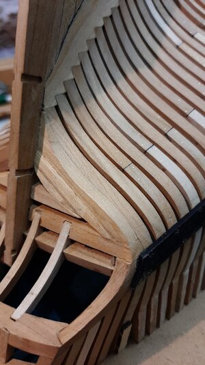
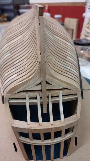
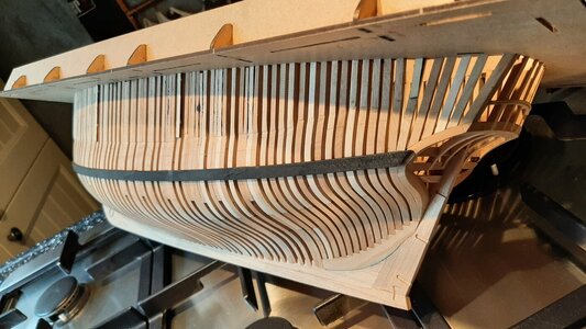
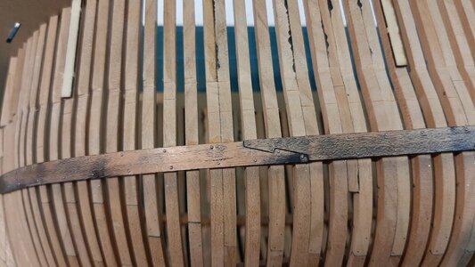
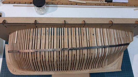
Hms Alert by Maarten [COMPLETED BUILD]

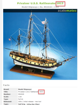
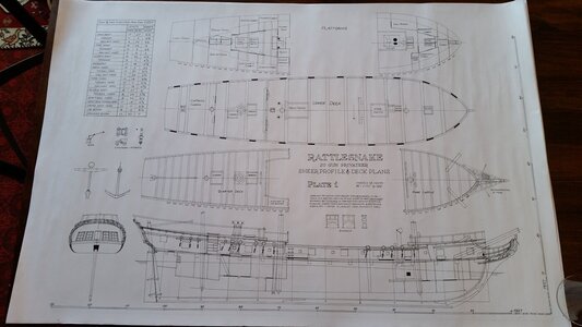
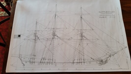
If this is the three masted US privateer, former Cormorant you can also have a look at the books of the Swan class ships which are of similar size as this Rattlesnake.
If it is the two masted brig Ratlesnake which is similar size as Alert you could use the data from the Alert book.
Very confusing subject ROTF Not only 2 but not less than 10 ships in the Royal Navy has been named HMS Rattlesnake according to Wikipedia:
1609939040739.png
Allegedly at least 2 of these (1783 & 1814) were both previously American and both captured by the Royal Navy.
According to Wikipedia both of them were brigs. AFAIK a brig has 2 mast so I guess at least for the HMS 1783/USS 1781 this must be wrong.
I think the one that Hahn build was the HMS 1783 / USS 1781 one.
Was the HMS 1783 / USS 1781 ever sold back to America? I could not find any evidence of that, but several sites seem to believe she ended up in France
It also seems that a lot of modelers and other people are mixing these 2 ships up. Just one example:
1609945730675.png

Sorry for the hijacking Maarten, just to show that the year along with the name is far from unimportant :-)
 
Back to Alert, which also had a sister called Rattlesnake :-) , to make it more complex.

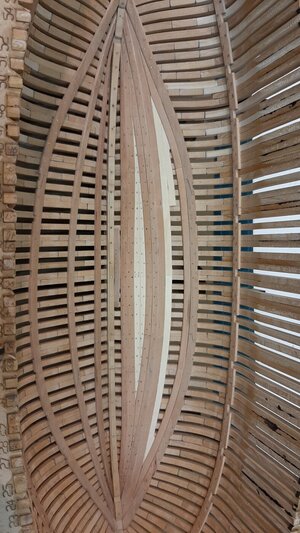
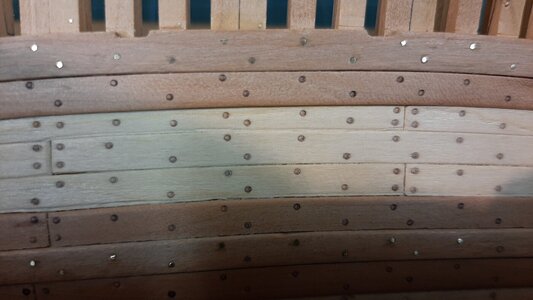
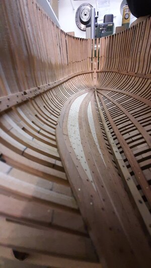
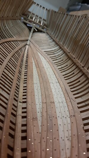
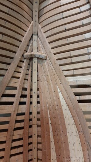
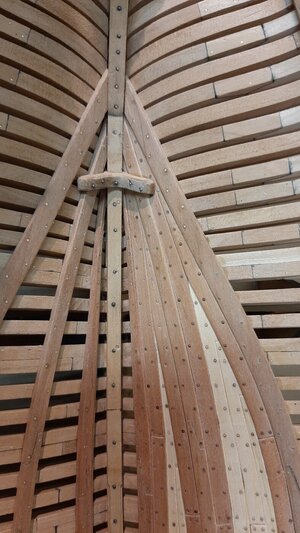
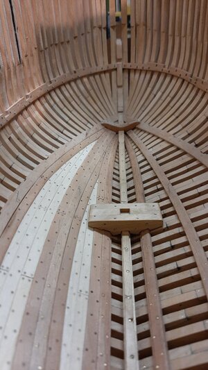
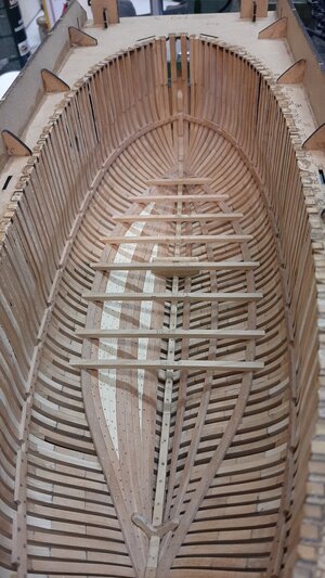
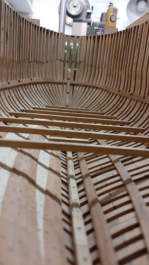
Stil working on the ceiling, laying planks in the second part.
20210104_212839.jpg

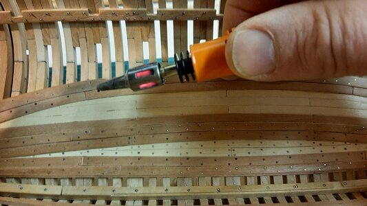
second part finished, time for making treenails.
20210106_195410.jpg

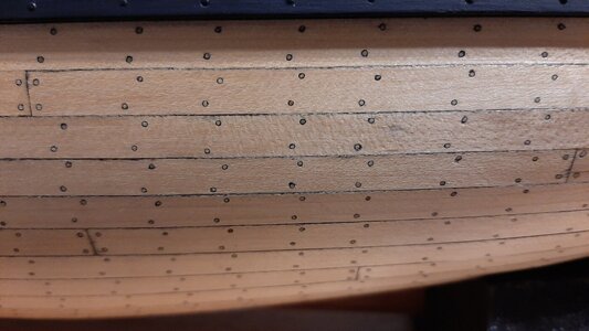
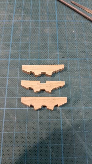
Treenails before sanding.
20210106_200552.jpg

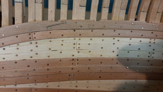
And after sanding.
20210106_202603.jpg

Compared to actual birchwood treenails on my Royal Caroline which is I think 50 x the work.
20210106_202528.jpg

And finished, one more to go.
20210106_201035.jpg20210106_201057.jpg
20210106_201258.jpg
 
@Maarten, the question is now solved, it is the three-masted American privateer, the former cormorant, I did not now that she had the name cormorant before, now I will see if I can find a suitable book about the Swan class, Uwe can probably help, thanks all the help, sorry for the burglary in your log.
RATTLESNAKE (1).jpgRATTLESNAKE (6).jpg
 
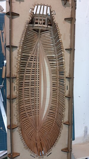
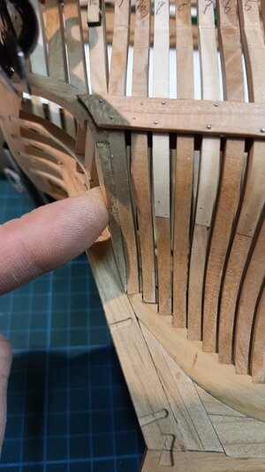
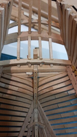
After filling in the first two areas between the thickstuff with ceiling planks it is now time for something else before finalizing the last ceiling.
I will fit the first knee in the stern and bow as well as the mast step.
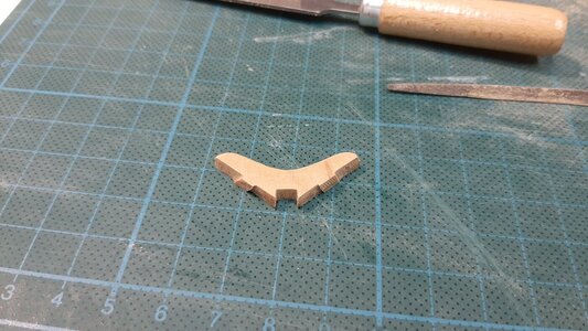
These knees are pre milled but need a lot of work to fit properly, especially on one side where I added the ceiling planks.
20210108_153051.jpg

After filing, fitting, filing, fitting etc it finally fits and is glued in place, bolted with 0,6 mm steel wire and left to dry.
20210108_165921.jpg
After drying the bolthead are cut and rounded with the cup burr.
20210108_165921.jpg

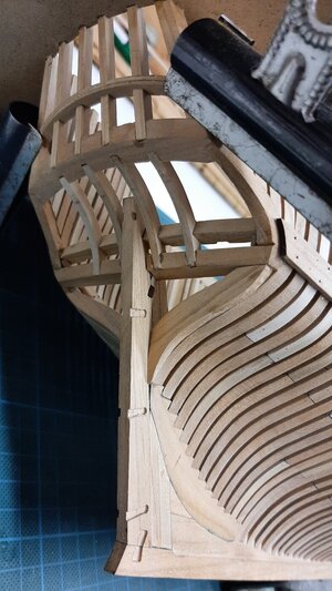
Next is the mast step, build from 3 parts. The top 2 are already modified for fitting my ceiling.
20210107_193611.jpg

After glueing, finishing and bolting fitting into the hull.
20210108_170013.jpg

Now I will temporary fit the lower deck beams, just trim and make these properly fit before finishing the ceiling.
20210110_142835.jpg
20210108_184345.jpg

If other Alert builders think what is he doing, the manual is showing other things, yes you are right. I don t follow the manual as I plan to do something different so I determined my own building sequence which will be different then the manual shows.

I removed the hull from the berth again and glue in the distance pieces for the template to mark the cutting spots for the frames.
20210110_144752.jpg

The template is fitted and at the marked positions I mark the frame with a knive.
20210110_145158.jpg

In the bow I drill the hawser hole position.
20210110_150058.jpg

After removing the template all the cutting spots are clearly marked.
20210110_150744.jpg

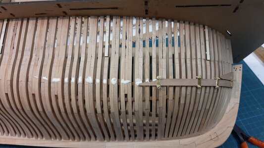
Now I will set out the main wale.
The cutting markers are the timber tops which I use as reference to determine the wale position.
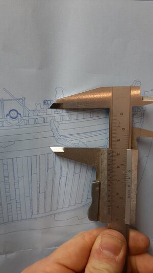
I recalculate the dimensions as the model is 1,031 x the drawing dimension.
20210110_165704.jpg

This I do at multiple frames and mark the wale lower edge into the frames.
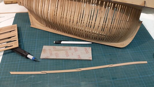
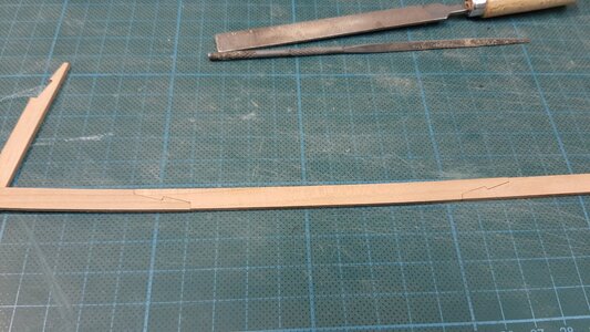
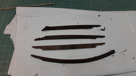
The wale is made of 4 scarphed planks and for these I make the scarph joints fit properly.
20210110_155629.jpg
20210110_163751.jpg

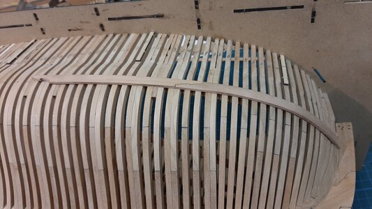
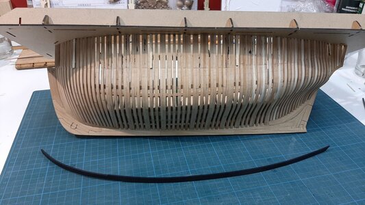
Then sanding followed by steaming them into the proper shape by steam and drying and bending on a heat plate.
A proper bend plank fit into place without applying to much pressure.
20210110_172553.jpg

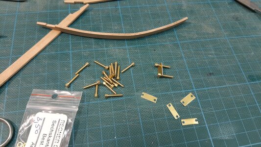
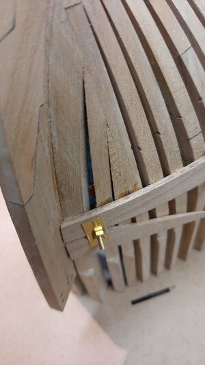
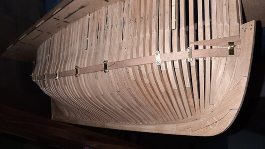
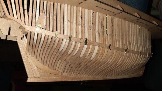
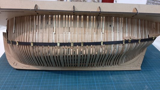
To glue the wale in place I made some DYI clamps from m2 bolts and brass plate.
20210110_175438.jpg

A single clamp at the bow.
20210110_191606.jpg

The first wale section glued and clamped, the second ready for fitting.
20210110_182814.jpg

All fitted with clamps in place to dry the pva glue in 24hrs.
20210110_191642.jpg

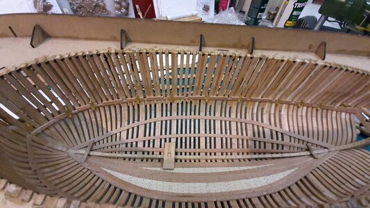
The clamps on the inside around the clamp shelf.
20210110_191724.jpg

Now ready for receiving the bolts after the glue has dried.
20210110_200937.jpg
20210110_201019.jpg
20210110_201234.jpg
 
After filling in the first two areas between the thickstuff with ceiling planks it is now time for something else before finalizing the last ceiling.
I will fit the first knee in the stern and bow as well as the mast step.
These knees are pre milled but need a lot of work to fit properly, especially on one side where I added the ceiling planks.
View attachment 204804

After filing, fitting, filing, fitting etc it finally fits and is glued in place, bolted with 0,6 mm steel wire and left to dry.
View attachment 204808
After drying the bolthead are cut and rounded with the cup burr.
View attachment 204809

Next is the mast step, build from 3 parts. The top 2 are already modified for fitting my ceiling.
View attachment 204810

After glueing, finishing and bolting fitting into the hull.
View attachment 204811

Now I will temporary fit the lower deck beams, just trim and make these properly fit before finishing the ceiling.
View attachment 204812
View attachment 204813

If other Alert builders think what is he doing, the manual is showing other things, yes you are right. I don t follow the manual as I plan to do something different so I determined my own building sequence which will be different then the manual shows.

I removed the hull from the berth again and glue in the distance pieces for the template to mark the cutting spots for the frames.
View attachment 204814

The template is fitted and at the marked positions I mark the frame with a knive.
View attachment 204815

In the bow I drill the hawser hole position.
View attachment 204820

After removing the template all the cutting spots are clearly marked.
View attachment 204821

Now I will set out the main wale.
The cutting markers are the timber tops which I use as reference to determine the wale position.
I recalculate the dimensions as the model is 1,031 x the drawing dimension.
View attachment 204822

This I do at multiple frames and mark the wale lower edge into the frames.
The wale is made of 4 scarphed planks and for these I make the scarph joints fit properly.
View attachment 204825
View attachment 204823

Then sanding followed by steaming them into the proper shape by steam and drying and bending on a heat plate.
A proper bend plank fit into place without applying to much pressure.
View attachment 204824

To glue the wale in place I made some DYI clamps from m2 bolts and brass plate.
View attachment 204826

A single clamp at the bow.
View attachment 204828

The first wale section glued and clamped, the second ready for fitting.
View attachment 204827

All fitted with clamps in place to dry the pva glue in 24hrs.
View attachment 204833

The clamps on the inside around the clamp shelf.
View attachment 204834

Now ready for receiving the bolts after the glue has dried.
View attachment 204835
View attachment 204836
View attachment 204837
Cool clamps! I learn something with every posting!
 
After filling in the first two areas between the thickstuff with ceiling planks it is now time for something else before finalizing the last ceiling.
I will fit the first knee in the stern and bow as well as the mast step.
These knees are pre milled but need a lot of work to fit properly, especially on one side where I added the ceiling planks.
View attachment 204804

After filing, fitting, filing, fitting etc it finally fits and is glued in place, bolted with 0,6 mm steel wire and left to dry.
View attachment 204808
After drying the bolthead are cut and rounded with the cup burr.
View attachment 204809

Next is the mast step, build from 3 parts. The top 2 are already modified for fitting my ceiling.
View attachment 204810

After glueing, finishing and bolting fitting into the hull.
View attachment 204811

Now I will temporary fit the lower deck beams, just trim and make these properly fit before finishing the ceiling.
View attachment 204812
View attachment 204813

If other Alert builders think what is he doing, the manual is showing other things, yes you are right. I don t follow the manual as I plan to do something different so I determined my own building sequence which will be different then the manual shows.

I removed the hull from the berth again and glue in the distance pieces for the template to mark the cutting spots for the frames.
View attachment 204814

The template is fitted and at the marked positions I mark the frame with a knive.
View attachment 204815

In the bow I drill the hawser hole position.
View attachment 204820

After removing the template all the cutting spots are clearly marked.
View attachment 204821

Now I will set out the main wale.
The cutting markers are the timber tops which I use as reference to determine the wale position.
I recalculate the dimensions as the model is 1,031 x the drawing dimension.
View attachment 204822

This I do at multiple frames and mark the wale lower edge into the frames.
The wale is made of 4 scarphed planks and for these I make the scarph joints fit properly.
View attachment 204825
View attachment 204823

Then sanding followed by steaming them into the proper shape by steam and drying and bending on a heat plate.
A proper bend plank fit into place without applying to much pressure.
View attachment 204824

To glue the wale in place I made some DYI clamps from m2 bolts and brass plate.
View attachment 204826

A single clamp at the bow.
View attachment 204828

The first wale section glued and clamped, the second ready for fitting.
View attachment 204827

All fitted with clamps in place to dry the pva glue in 24hrs.
View attachment 204833

The clamps on the inside around the clamp shelf.
View attachment 204834

Now ready for receiving the bolts after the glue has dried.
View attachment 204835
View attachment 204836
View attachment 204837
Dear Maarten
it's looks magnificent :)OkayThumbs-Up
Thanks for the detailed explanations and photos
 
'Black' background. you are learning fast, Mon Amie!!! What was the reason drifted from the manual course? Will you paint 'black' the wales?
The black background is due to the flash, I just took it in the livingroom with dimmed light.

Why deviating from the manual. First of all I am not such a manual guy, just build and see. But as I will add the outer skin on one half I want to have it on before starting on the inside, otherwise you will get a hudge amount of dust and particles in the interior which will be difficult to remove afterwards. So first I do all the major construction works and sanding. Secondly I still need the space on the inside and also sufficient rigidity of the hull without deckbeams fitted, but I will explain that later.

The wales, one side of the ship will show the plain wood construction, frames, deckbeams, bulkheads, this side will be unpainted or coloured. The other halfside will be fully build, coloured and decorated.
The current wale will be plain, the other one black.
Some painted friezes, perhaps?:cool: You are doing such a fine job with this cutter. Beautiful!
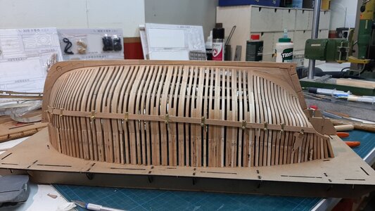
 
Very good work - and thanks for sharing the idea with these brass clamps ! Very good idea for planks like the wales where you have both sides available and on the other side another clamp-plank has to be inside the frames on the same levels - I have to keep this idea in mind for future problems :cool:
 
Last edited:
Thx gents for your comments. Thx to SOS we all pick up new ideas and techniques.
Today only some minor progress but still a few hours of work.
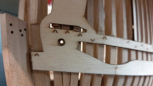
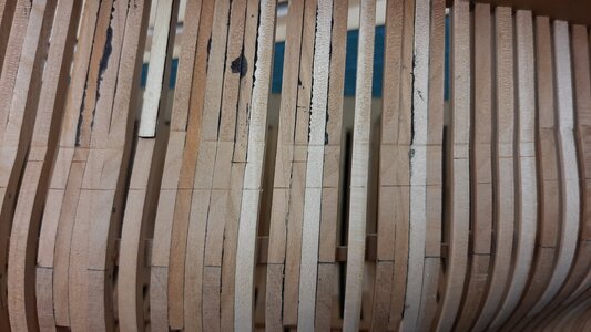
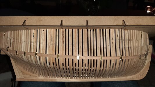
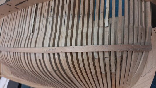
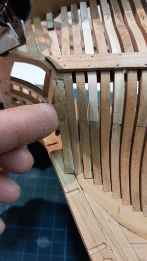
The clamps are removed from the wale, holes drilled and 0,6 mm wire fitted as bolts. Again the wires were finished with a cup burr which finalizes the SB wale. According the drawings and other data I could find the bolts are more or less fitted at every second frame. I have to figure out if the in between frames were maybe tree nailed as is done with the hull planking, maybe someone has more data on this? You can also see the markings for the frame cutting clearly.
20210112_204136.jpg

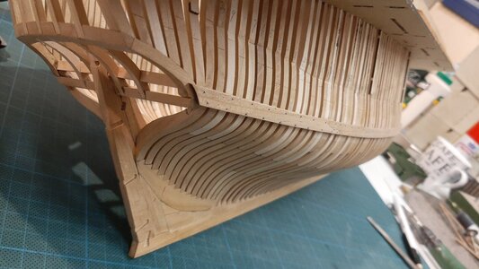
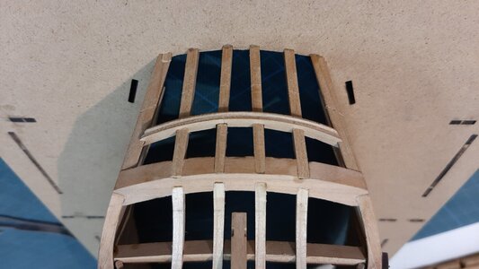
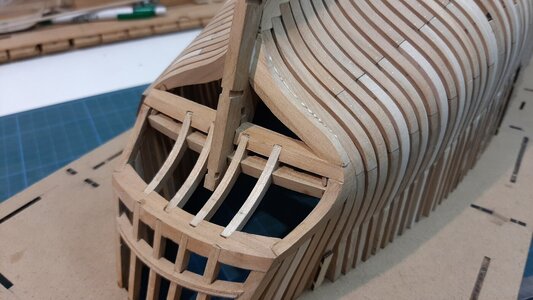
Before continuing on the PS wale I will first work on the stern. After marking the stern cutting spots I have removed the guidence pieces for building up the stern transome so now the stern is also completely free from MDF templates showing it beautifull lines fully.
20210112_213214.jpg

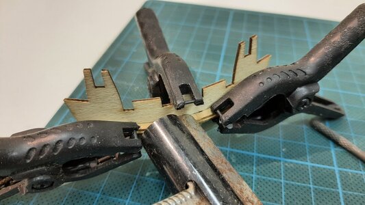
I am working on the tafrail which consist of two parts which first need bending into shape followed by glueing together. To get the correct curvature I use the provided template which I first bend into the stern curvature.
20210112_210942.jpg

I also use the template as a clamp to glue the two layers of the tafrail together.
20210112_213242.jpg

Now that has to dry for 24 hrs so that is it for today.
 
Last edited:
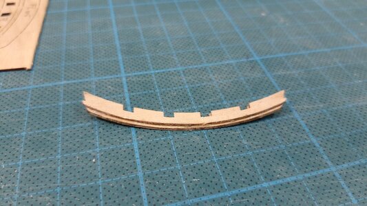
The freeze is dry in the meantime so lets continue. As I glued the two curved pieces together you get a nice solid curved part.
20210114_192629.jpg
According the drawings the freeze should get a curved edge which I create with a round jewelers file. The the outer edges should be filed in the correct angles to get a proper fit in the transome.
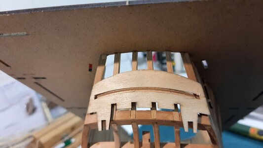
During dry fitting the part you see it neatly fits into the template.
20210114_201317.jpg
Finally fitting the parts. Pictures from multiple angels show you the shape of this part.
20210114_201355.jpg20210114_201407.jpg20210114_201420.jpg

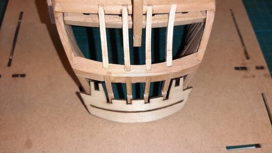
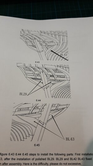
Next is work on the fashion pieces BL 42, these get an additional half frame which has to be sanded into shape at multiple angles.
20210114_202458.jpg
I first sand the angles fitting to the stern and the upper transome. Then it can be dry fitted to mark the lower and upper dimension.
20210114_202935.jpg

Now I sand it in the correct angle towards the marked dimension on the discsander.
20210114_203431.jpg
20210114_203630.jpg
Now glue it in place, the rest of the trimming I do when the part is fixed.
20210115_174010.jpg

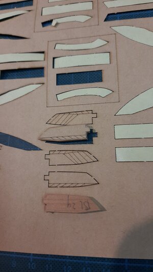
Now the lower transome parts BL29, these also have multiple angled surfaces but a sticker template is provided to give the the right shape.
20210115_202652.jpg20210115_203222.jpg20210115_203227.jpg
The right shape, still a lot of trimming is needed.
But they fit allthough the SB one needs some fine tuning. I clamped them with some wood strips during drying. An additional transome part will be fitted after the glue dried, then final trimming is done.
20210115_211615.jpg

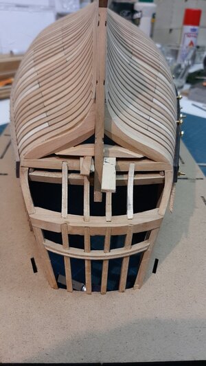
On the inside I now have a nice edge to fit the ceiling planks onto, this is one of the reasons why my build is totally not following the manual anymore.
20210115_211539.jpg

At last I also prepared the PS wale after scarph trimming, steaming, bending and colouring it with black Ecoline ink it is time to fit it.
20210115_171700.jpg20210115_193622.jpg20210115_202325.jpg

Now it is time to dry the glue before we can continue.
Enjoy your builds.
 
Work on the lower transom continues.
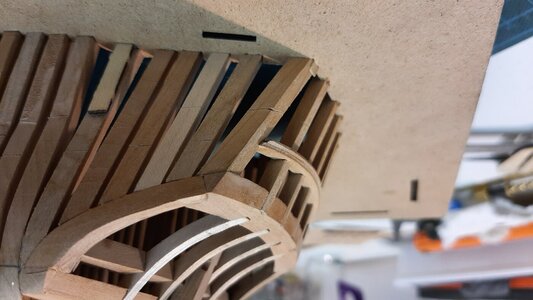
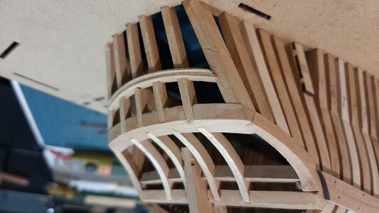
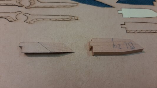
The last part to be added is BL 43 which is glued on top of BL42.
20210118_175014.jpg

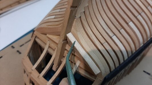
This part has a lot of additional meat which needs to be trimmed. Again first the part joining to the stern should be trimmed so the part is properly fitting in place on top of BL 42. Then the rest of the parts should be trimmed to follow the outlines of the lower transom, to these the stern planking will be fitted.
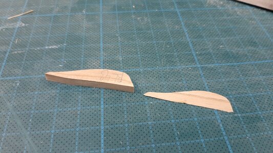
Below you see the part trimmed and untrimmed and you directly see how much material is removed. I did this by using my disc sander.
20210118_174930.jpg

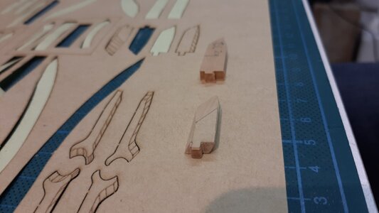
The final trimming I do when the part is glued in place so you have optimum control over the shape of the stern. So now I glued the part in place.
20210118_175646.jpg

Followed by preparing and glueing the SB piece.
20210118_181806.jpg

While these two parts dry further work on the wale is done.
The clamps are removed.
20210116_114327.jpg

And the wale is filed towards a flat and smooth surface removing the imperfections from the fitting process. Now holes for the bolts are drilled and again 0,6 mm anealed steel wire fitted and cut. The finish of the bolts again with a cup burr.
20210118_213458.jpg
20210118_213504.jpg

When all bolts are finished I will once sand the wale with steel wool followed by a final layer of black Ecoline ink. This is later finished and sealed with oil.
 
Back
Top